
Want to protect our home or room from intruders? then this simple IR Burglar Alarm Circuit is our smart security buddy!
It uses invisible IR light to sense any movement or break in the beam; the moment someone crosses the path, a loud buzzer alerts us instantly.
Moreover, its easy to build, with low cost and perfect for beginners in electronics!
Circuit Working:
Parts List:
| Components | Values | Quantity |
|---|---|---|
| Resistors | 100Ω, 1/4 watt | 1 |
| 1k | 1 | |
| Variable Resistor Preset 50k | 1 | |
| Semiconductors | Transistor BC557 PNP | 1 |
| Phototransistor L14F1 | 1 | |
| Infrared LED (IR LED) | 1 | |
| Buzzer 3 to 12V DC | 1 | |
| Battery 9V | 1 |
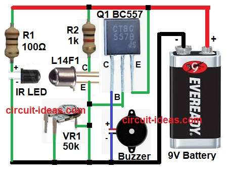
IR LED sends invisible infrared light continuously and phototransistor L14F1 receives this IR light.
When an object or person blocks the IR light, the BC557 transistor activates, turning ON the buzzer and producing an alarm sound and when nothing blocks the IR beam, the phototransistor keeps the BC557 transistor OFF and the buzzer remains silent.
Also, the 50k variable resistor VR1 controls the sensitivity of the circuit and IR LED, then resistor R1 100 ohm limits the current to safe value and R2 1k resistor works as a load resistor for the phototransistor L14F1.
Finally, it helps convert light signal into voltage signal.
Formulas:
Below is the formula with calculation for IR Burglar Alarm Circuit:
Current through IR LED.
I = V / R
= (9V – 1.2V) / 100 ohm = 78 mA approx
This current is enough for IR transmission.
How to Build:
To build a IR Burglar Alarm Circuit following steps we need to follow:
- First, connect IR LED anode to 9V through R1 resistor and then IR led cathode connect to GND.
- After that, L14F1 collector connect to 9V through 1k R2 resistor and then connect emitter to base of transistor Q1 and one end of preset 50k VR1 and other end of VR1 connect to GND.
- Now emitter of BC557 connect to +9V supply and then collector of BC557 connected to one terminal of buzzer.
- Also, other terminal of buzzer connect to GND.
- Then connect 9V battery positive to positive of the circuit and negative of 9V battery connect to GRN of the circuit.
Conclusion:
Overall, this IR Burglar Alarm Circuit is cheap and easy to make and it detects movement or interruptions in the IR beam; we can also adjust the sensitivity by changing VR1.
Therefore, this circuit is useful for home, shop or lab security.