
Make your led blink easy with this easy to make Low Power Led Flasher Circuit using Nand Gate IC, as it uses IC CD 4093, a quad Nand gate with Schmitt trigger input.
Also, the circuit makes led blink with very less power and it can run from small 6V battery too.
Circuit Working:
Parts List:
| Components | Values | quantity |
|---|---|---|
| Resistors | 330k ohm 1/4 watt | 1 |
| 330 ohm 1/4 watt | 1 | |
| Capacitors | Electrolytic 10uF 10V or 16V | 2 |
| Semiconductors | IC CD 4093 | 1 |
| Diode 1N4148 | 1 | |
| LED any color | 1 | |
| Battery 6V | 1 |
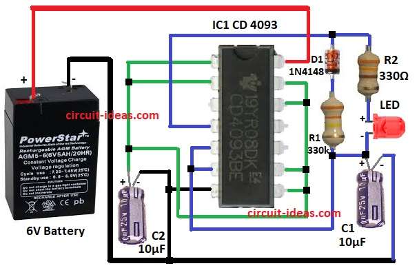
The circuit diagram above uses one NAND gate from the CD4093 IC, which contains four NAND gates.
By connecting pins 1, 2, 8, 9, 12, and 13 together, the circuit makes the NAND gates operate as inverters.
Then capacitor C1 and resistor R1 make timing network and when power is ON, C1 capacitor charge through R1 and diode D1 and this makes input change slow and Schmitt trigger make output change fast after one level.
So led blink ON and OFF.
Diode D1 gives fast discharge for C1 so duty cycle is correct and then resistor R2 limit current of LED
Formula:
Formula for time period t = 0.693 × R1 × C1
Frequency f = 1 / t
here,
- R1 is 330k
- C1 is 10uF
t = 0.693 × 330000 × 0.00001 = 2.28 seconds approx
So LED will flash around every 2.3 second
How to Build:
To build a Low Power Led Flasher Circuit using Nand Gate IC following are the steps to follow:
- First, take all parts same like in circuit picture.
- Next, connect pin 1,2,8,9,12,13 of IC 4093 to + of 6V battery and + of capacitor C2 and negative of C2 goes to ground.
- Then connect pin 7 of IC to ground and then connect pin 14 of IC to + of 6V battery.
- After that, connect pin 4 of IC to point of diode D1, resistor R2 and anode of LED.
- Join pin 5 and pin 6 together.
- Put diode D1 and resistor R1 between pin 4 and pin 6.
- Finally, connect + of capacitor C1 to cathode of LED and negative of C1 goes to ground.
Conclusion:
Overall, this low-cost, low-power LED flasher circuit uses a NAND gate and requires only one IC, two capacitors, two resistors, one diode, and one LED.
Moreover, hobbyists can use this circuit in small toys, indicators and other hobby projects.