Want to try to make DIY Simple Electric Guitar Circuit from Hawaiian guitar? then this article can help, it is very good idea and cheap also which anybody can try.
What is Electric Guitar:
Electric guitar is guitar that take sound from strings like steel or nickel and change into electric signal using sensor, then signal goes to amplifier and then this amplifier makes sound big and come out from speaker.
Circuit Working:
Parts List:
| Components | Values | Quantity |
|---|---|---|
| Amplifier Unit | 1 | |
| 230V AC Electromagnet | 1 | |
| Speaker | 1 | |
| Coaxial Wire | Set includes cables | 1 set |
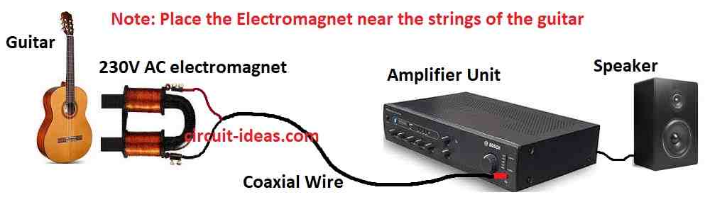
For the above circuit diagram, we need just one door bell electromagnet working on 230V AC and one transistor receiver or normal audio amplifier.
First, place the electromagnet near guitar or banjo wires and be sure wires go same way like parallel with the poles but not touching.
Now electromagnet work like pick-up coil and will turn ON amplifier and now connect coils two ends to amplifier input; set volume nice and comfortable and then plays the guitar.
Now guitar sound come from amplifier speaker and try to move coil little bit here and there until sound come best.
Also, when sound is good then fix coil tightly and use insulated wire for coil or else it can make unwanted noise.
After that, put strong permanent magnet near electromagnet core and this will give more sound like high output.
Formula:
Below formula show how strong the magnetic field (B) is in electromagnet or solenoid:
B = (1.257 * 10⁻⁶ * Ur * I * N) / L (f1)
Here what all these mean:
- B shows magnetic field strength measured in tesla T.
- 1.257 * 10⁻⁶ is a constant (µ₀) which shows how empty space let magnetic field connect to electric current.
- Ur is thickness or type of core material.
- I is current going through coil in ampere.
- N is number of turns or spins in coil.
- L is length of the core in meters.
What this mean in actual life:
More current = stronger magnetic field.
More coil turns = stronger field.
Better core material (Ur) = stronger field.
Shorter core = stronger field.
Hence, this formula help in many works when using electromagnets.
How to Build:
To Build a Simple Electric Guitar Circuit following are the building steps for connections:
Electromagnet Position:
- First, put electromagnet near the wires of guitar or banjo and be sure wires go same direction in parallel with electromagnet poles but not touching.
Making the Pick-Up Coil:
- Now electromagnet works like pick-up coil and then take coils two ends and connect to amplifiers input.
Connections:
- After that, use insulated wire to stop unwanted noise and connect shielded wire from coil to input side of amplifier.
Set Up Amplifier:
- Next, turn amplifier ON and adjust volume knob to get sound level we like.
Check and Adjust:
- Now, play the guitar and we can hear sound coming louder from speaker, if required move coil a little bit and try different positions, also find spot where sound is best.
Fix in Place:
- Also, when sound is good fix electromagnet tightly in that place.
Extra Improvement (Optional):
- If required, put one strong permanent magnet very close to electromagnet core and this will give more loudness and better output.
Final Test:
- Finally, play instrument again and see if sound and tone is what we want.
Conclusion:
Overall, be careful when touching electric parts and be sure electromagnet and amplifier are safe to use.
Also, if we do not know how to do it, ask someone who knows electronics, also this Simple Electric Guitar Circuit works in many music styles like pop, jazz, rock, and blues.
Furthermore, because guitar is flexible, musicians can use pedals and amps to try different sounds and effects.

Leave a Reply