Tachometer is tool to check how fast motor shaft or disk spin.
Speed is shown in RPM (revolutions per minute).
This article for Measuring RPM with a Tachometer Circuit teaches us how simple tachometer circuit made, how it work and how to build it.
Tachometer are used in many places like industry, car and lab to check speed of rotating parts.
It give important information to help control and improve machine work.
This circuit uses simple parts to check motor RPM.
It work with 12V DC power and show reading on analog meter.
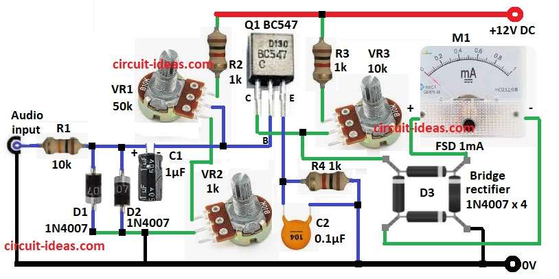
Circuit Working:
Parts List:
| Component | Value/Type | Quantity |
|---|---|---|
| Resistors | 10k 1/4 watt | 1 |
| 1k 1/4 watt | 3 | |
| Potentiometers 50k, 1k, 10k | 1 each | |
| Capacitors | Ceramic 0.1μF | 1 |
| Electrolytic 1μF 25V | 1 | |
| Semiconductors | Transistor BC547 | 1 |
| Diodes 1N4007 | 2 | |
| Bridge Rectifier 1N4007 diodes | 4 | |
| Analog Meter 1mA FSD meter | 1 |
Input signal show pulses from spinning thing like motor.
Signal can come from magnetic pickup or Hall sensor and both make good pulses.
Diodes D1 and D2 change signal and only let positive pulses go ahead.
Capacitor C1 smooth the pulses and resistor R1 stop too much current.
Strong pulses go to transistor Q1 base and Q1 make signal stronger for next parts.
VR1 is potentiometer which changes how much Q1 amplifies signal.
Then capacitor C2 and resistor R4 filter pulses again to make steady DC voltage and this voltage match motor RPM.
Bridge rectifier D3 prepare signal for analog meter M1.
At the end analog meter show DC voltage and this tell user the motor RPM, simple and clear.
Formulas with Calculations:
Use these formulas to check RPM using tachometer circuit:
1. Frequency to Voltage:
Vout = Im × Rload
where,
- Im is the current in meter
- Rload is the total resistance in circuit
2. Capacitor Size (for filter):
fc = 1 / (2 × pi × R × C)
where,
- fc is the cutoff frequency
- R is the resistance in ohms
- C is the capacitor in farads
This help remove high frequency noise but still keep RPM reading correctly.
How to Build:
To measure the RPM with a Tachometer Circuit following steps are needed to follow:
- Collect all parts shown in circuit diagram.
- Connect base of Q1 to middle leg of VR1.
- Top leg of VR1 goes to one end of R2 and other end of R2 to +12V.
- Bottom leg of VR1 connect to top leg of VR2.
- Collector of Q1 go to middle leg of VR3.
- Top leg of VR1 also connect to one end of R3 and other end of R3 to +12V.
- From base of Q1 connect C1, D1, D2 and R1 in series to Audio input and GND.
- Emitter of Q1 connect to R4 and C2 in parallel and then it goes to GND.
- One pin of D3 bridge rectifier goes to Q1 collector, second pin goes to positive of of M1 meter, third pin goes to negative of M1 and pin fourth goes to GND.
Safety Rules:
- Be careful always when using this circuit.
- Spark plug gives high voltage and turns OFF engine before connecting anything.
- Avoid electric shock and stay alert.
- Try this on car only if anyone know car wiring well.
- The author is not responsible if accident happen, so always be safe.
Conclusion:
This Measuring RPM with a Tachometer Circuit is cheap and easy way to check how fast motor spin.
It uses simple parts, easy to find and works good.
It can be used in many projects but we should test and adjust before actual use.
This circuit is good for hobby people and learners who want to make and know about tachometer.
Leave a Reply