• Skip to primary navigation
  • Skip to main content
  • Skip to primary sidebar

Circuit Ideas for You

Get free circuit ideas online.

  • Home
  • Privacy Policy
  • About
Home » Natural Bird Sound Generator Circuit using Transistors

Natural Bird Sound Generator Circuit using Transistors

Last updated on 1 December 2025 by Admin-Lavi Leave a Comment

This is a small Natural Bird Sound Generator Circuit using Transistors.

The circuit uses two BC547 transistors, some resistors, capacitor and a speaker.

It is simple for beginners and works on low voltage like 3V to 9V.

Circuit is good for toys, hobby projects, alarms and for school projects.

Circuit Working:

Natural Bird Sound Generator Circuit Diagram using Transistors

Parts List:

ItemValueQuantity
Resistors100k2
470Ω, 1k1 each
Capacitors Electrolytic 470uF 25V, 330uF 25V1 each
Ceramic 0.1uF1
SemiconductorsTransistors BC547, BC5571 each
Speaker 8 ohm small1
Push button Switch1
Battery 9V1

This circuit uses two transistors BC547 and BC557.

It use 4 resistors to control sound.

It uses two big capacitors 330uF and 470uF and one small 0.1uF.

A small 8-ohm speaker make the bird sound.

A push button connect battery power.

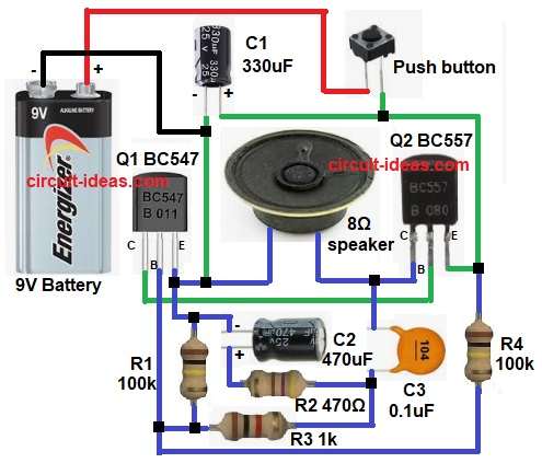
Wires connect all parts same like in circuit diagram above.

BC547 make fast sound.

BC557 make slow up-down effect.

How to Build:

To build a Natural Bird Sound Generator Circuit using Transistors follow the below steps:

  • First collect all parts same like circuit diagram above.
  • Join BC547 Q1 collector to BC557 Q2 base.
  • Join Q1 base to one side of R1, R2 and R4.
  • Join other side of R1, R2, R3 to positive side of C2 and C3.
  • Join Q1 emitter to positive of C1, C2, R1 and one side of 8 ohm speaker.
  • Join Q2 collector to other side of 8 ohm speaker and one side of C3.
  • Join Q2 emitter to one side of switch and negative of C1.
  • Join 9V battery positive to switch and battery negative to C1 negative.

Conclusion:

This is simple low cost Natural Bird Sound Generator Circuit using Transistors.

It uses only two common transistors and few parts.

Works on small battery power.

Good for electronics learning and fun projects.

We can change resistor and capacitor values to make different bird sounds.

References:

How does this tone generator circuit work?

Filed Under: Audio Circuits, Transistor Circuits

About Admin-Lavi

Lavi is a B.Tech electronics engineer with a passion for designing new electronic circuits. Do you have questions regarding the circuit diagrams presented on this blog? Feel free to comment and solve your queries with quick replies

Previous Post: « Arduino Chirping Bird Sound Circuit
Next Post: 7812 Based 12 Volt DC Power Supply Circuit »

Reader Interactions

Leave a Reply Cancel reply

Your email address will not be published. Required fields are marked *

Primary Sidebar


Categories

  • Alarm Circuits (45)
  • Amplifier Circuits (67)
  • Arduino Projects (99)
  • Audio Circuits (114)
  • Automobile Circuits (19)
  • Battery Charger Circuits (65)
  • Free Energy (13)
  • Heater and Temperature Controllers (13)
  • High Voltage (1)
  • Indicator Circuits (45)
  • Inverter Circuits (20)
  • IoT projects (1)
  • LDR Circuits (26)
  • LED and Lamps (148)
  • Meters and Testers (30)
  • Motor Controllers (22)
  • Oscillator Circuits (39)
  • Power Supply Circuits (104)
  • Remote Control Circuits (10)
  • Security and Protection (29)
  • Sensors and Detectors (126)
  • Solar Circuits (29)
  • Timer Circuits (41)
  • Transistor Circuits (87)
  • Transmitter Circuit (17)
  • Tutorials (8)
  • Water Level Controller (6)

Recent Posts

  • 12V Battery Low Voltage Alarm Circuit
  • Low Voltage Alert Circuit for 9V Battery
  • Digital Code Lock Circuit using IC 4017
  • Darkness Activated LED Circuit
  • Fan Start 10 Second Delay Timer Circuit

Recent Comments

  1. TDHofstetter on DIY Variable Power Supply Circuit using Arduino
  2. feathbuff on Simple Micro Ampere Meter Circuit
  3. Admin-Lavi on Simple School Project Multimeter Circuit
  4. choke on Simple School Project Multimeter Circuit
  5. Admin-Lavi on Analog to Digital Converter Circuit using IC 555

Copyright © 2026 | New Circuit Ideas