In this article, a temperature to voltage converter circuit converts temperature change into proportional voltage output.
An NTC thermistor senses the temperature and the 741 op-amp converts the resistance change into a voltage signal, as the temperature changes, the output voltage also changes in a linear way.
Therefore, this NTC thermistor based temperature to voltage converter circuit is useful for temperature monitoring, control systems, battery temperature sensing and industrial automation projects.
Moreover, the circuit gives around 0.5V output change for every 1°C temperature change, as shown in the below diagram and because of this, it becomes easy to connect the output with ADC, microcontroller, comparator or relay driver circuit.
Circuit Working:
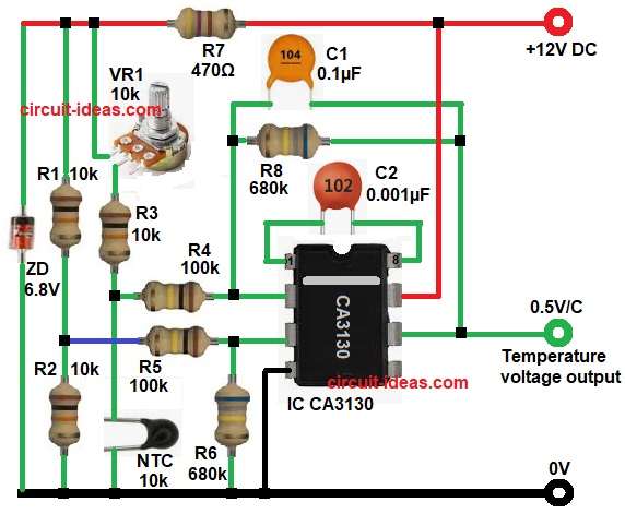
Parts List:
| Components | Values | Quantity |
|---|---|---|
| Resistors (All resistors are 1/4 watt) | 10k | 3 |
| 470Ω | 1 | |
| 100k, 680k | 2 each | |
| Potentiometer 10k | 1 | |
| NTC Thermistor 10k | 1 | |
| Capacitors | Ceramic 0.1µF, 0.001µF | 1 each |
| Semiconductors | Zener Diode 6.8V | 1 |
| IC CA3130 / LM741 | 1 | |
| Power Supply +12V DC | 1 |
First, the NTC thermistor works as the temperature sensing element, its resistance decreases when temperature increases, so when the surrounding temperature rises the resistance of the NTC falls.
Next, resistors R1 and R2 create a fixed reference voltage, at the same time VR1, R3 and the NTC branch create a temperature dependent voltage.
Then the IC CA3130 op-amp compares the reference voltage at the non-inverting input of pin 3 with the temperature-based voltage at the inverting input pin 2.
As the temperature changes the voltage difference between pin 2 and pin 3 changes and because of this difference the op-amp output at pin 6 changes proportionally.
After that, feedback resistor R8 680k helps stabilize the gain and improves linearity an also capacitor C1 removes noise and improves output smoothness.
Finally, the circuit gives an output sensitivity of nearly 0.5 V/°C, so if temperature increases by 1°C then output voltage rises by around 0.5 V.
Note: LM741 IC also can be used in this circuit because pinout and working function of both the ICs are same.
How to Build:
To build a NTC Thermistor Based Temperature to Voltage Converter Circuit follow the below connection steps:
- First, assemble all the components on the PCB board.
- Next, take IC CA3130 and join pin 1 and pin 8 through capacitor C2.
- Then take pin 2 and join it to resistor R4 and this resistor comes from the temperature sensing network using VR1, R3 and the NTC thermistor.
- After that, take pin 3 and join it to resistor R5 and this resistor comes from the reference divider network using R1 and R2.
- Then connect resistor R6 from pin 3 of the IC to ground.
- Next, connect pin 4 directly to ground.
- Then take pin 6 which is the output pin and take the temperature voltage output from here.
- Next, take pin 7 which is the +V pin and join it to the +12V supply.
- After that, connect resistor R8 and capacitor C1 in parallel between pin 6 and pin 2.
- Then take Zener diode and connect cathode end to positive supply and anode to ground of the circuit.
- And then connect resistor R7 between VR1 potentiometer and capacitor C1 at positive supply.
- Finally, use VR1 and adjust the output voltage for the required temperature range.
Conclusion
This NTC Thermistor Based Temperature to Voltage Converter Circuit gives a simple and effective way to convert temperature changes into analog voltage output.
Since it uses an op-amp and NTC thermistor, the circuit remains easy to build and low in cost.
Furthermore, the output can directly interface with ADC, comparator, relay or microcontroller systems.
Therefore, this circuit is highly useful for temperature alarm systems, fan controllers, industrial monitoring and sensor-based automation applications.