
Turn Arduino into a motion spy! with just a PIR sensor, buzzer and LED we can detect movement easily.
Whenever someone passes, it spots movement and warns us with light and sound; this PIR Motion Detector Circuit using Arduino is for beginners and makers.
Also, it is fast to build, fun to use and full of learning.
Arduino Code:
int pirPin = 2;
int buzzer = 3;
int led = 4;
int pirState = LOW;
int val = 0;

void setup() {
pinMode(pirPin, INPUT);
pinMode(buzzer, OUTPUT);
pinMode(led, OUTPUT);
Serial.begin(9600);
}

void loop() {
val = digitalRead(pirPin);
if (val == HIGH) {
digitalWrite(buzzer, HIGH);
digitalWrite(led, HIGH);
if (pirState == LOW) {
Serial.println("Motion detected!");
pirState = HIGH;
}
} else {
digitalWrite(buzzer, LOW);
digitalWrite(led, LOW);
if (pirState == HIGH) {
Serial.println("Motion ended!");
pirState = LOW;
}
}
}
Coding Explanation:
- pinMode set input or output pins.
- loop read PIR pin.
- If PIR is HIGH then buzzer and LED is ON.
- If PIR is LOW then buzzer and LED goes OFF.
- pirState used to print message only once on change.
Circuit Working:
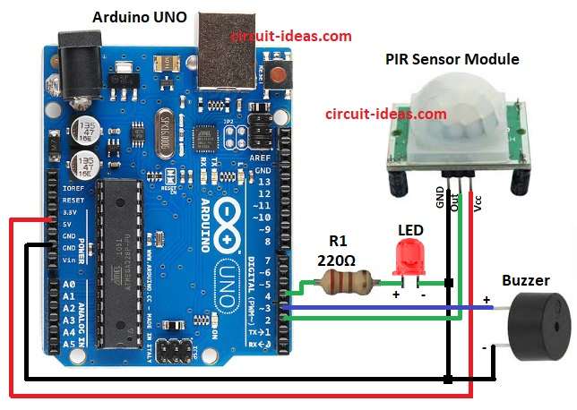
Parts List:
| Components | Quantity |
|---|---|
| Resistor 220Ω 1/4 watt | 1 |
| Arduino UNO | 1 |
| PIR Sensor Module | 1 |
| Any LED 5mm 20mA | 1 |
| Buzzer | 1 |
The above circuit diagram shows the Arduino motion detector using PIR sensor, LED and buzzer.
Then PIR sensor detect infrared from human body and if motion detects, it send HIGH signal to Arduino pin 2 and Arduino then turn ON buzzer and LED.
After some seconds it turn them OFF again and if there is no motion then buzzer and LED stays OFF.
Formula:
Below is the formula for PIR Motion Detector Circuit:
Use Ohm Law formula : R = V/I
where,
- R is the resistance in ohms Ω
- V is the voltage in volts V
- I is the current in amperes A
How to Build:
To build a PIR Motion Detector Circuit using Arduino follow the below steps for connections:
- First, gather all the parts as shown in circuit diagram.
- Next, PIR VCC pin connected to Arduino 5V, PIR GND pin connects to Arduino GND and PIR OUT pin connects to Arduino digital pin 2.
- Then buzzer positive connect to Arduino pin 3 and buzzer negative connect to GND.
- After that, LED positive connect to Arduino pin 4 through resistor R1 220 ohm and LED negative connect to GND.
- Finally, Arduino 5V and GND connect to breadboard power rails.
Conclusion:
Overall, this project is simple PIR Motion Detector Circuit using Arduino, it uses PIR to sense human movement.
Furthermore, Arduino control buzzer and LED alarm and this circuit is also good for home security and for automation.