The circuit control lamp brightness with PWM, and it is good for adjusting incandescent lamp light; also it uses 555 timer as astable multivibrator to control low-power lamp.
PWM controls power to lamp and changes brightness easily and this PWM Based Lamp Brightness Controller Circuit runs on 6V battery and works for many lighting needs.
Circuit Working:
Parts List:
| Components | Values | Quantity |
|---|---|---|
| Resistors (All resistors are 1/4 watt unless specified) | 10k | 1 |
| 47k | 1 | |
| 1.5k | 1 | |
| Potentiometer 470k | 1 | |
| Capacitors | Ceramic 22nF | 1 |
| Electrolytic 100µF 25V | 1 | |
| Semiconductors | IC 555 Timer | 1 |
| Transistor BD681 | 1 | |
| Diode 1N4148 | 2 | |
| Switch ON/OFF | 1 | |
| Lamp Incandescent 6V / 200 mA | 1 | |
| Battery 6V | 1 |
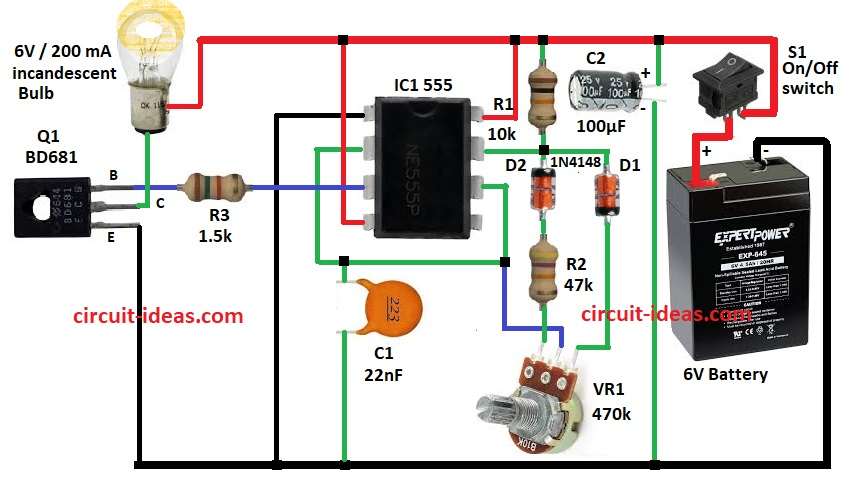
To begin with, circuit uses IC 555 in astable mode to make PWM signal and this PWM controls brightness of incandescent lamp.
Also, R1, R2, VR1 and C1 set oscillation speed and D1, D2 make uneven duty cycle so brightness changes by adjusting R2.
Then PWM from pin 3 drives transistor Q1 which controls lamp current and C2 keeps power supply stable.
So change R2 which changes duty cycle and also changes lamp brightness.
Formulas with Calculations:
Formulas for PWM lamp controller with 555 timer:
TON = 0.693 × R1 × C1
TOFF = 0.693 × R2 × C1
Frequency = 1 / (TON + TOFF)
Duty Cycle (%) = (TON / (TON + TOFF)) × 100
Therefore, change R2 which will change TOFF and this will change duty cycle with change in lamp brightness.
How to Build:
To build a PWM Based Lamp Brightness Controller Circuit follow below steps for connection:
- First, assemble all parts as per circuit diagram.
- Next, pin 1 of IC 555 goes to GND.
- After that, pin 2 and pin 6 connect together.
- Now pin 3 connects to base of Q1 via R3.
- Also, pin 4 and pin 8 connects to positive supply.
- Then R1 goes from pin 7 to positive supply and then C1 goes from pin 2 to GND.
- Further, D1 and D2 connects in series from pin 7 and also cathode of D1 goes to one end of VR1 and anode of D1 goes to pin 7.
- Also, cathode of D2 connects to pin 7, anode of D2 goes to one end of R2 and other end of R2 goes to VR1.
- Emitter of Q1 goes to GND and also collector of Q1 connects to one end of lamp and other end of lamp goes to positive supply.
- Finally, On/Off switch goes between positive supply and +6V battery and battery negative goes to GND and then C2 goes to positive supply and negative goes to GND.
Conclusion:
To conclude, PWM Based Lamp Brightness Controller Circuit is for low power use.
If required, change R2 it changes duty cycle and adjust brightness; also this circuit is good for small lighting, saves energy while keeping right light level.