• Skip to primary navigation
  • Skip to main content
  • Skip to primary sidebar

Circuit Ideas for You

Get free circuit ideas online.

  • Home
  • Privacy Policy
  • About
Home » Regulated 9V Power Supply Circuit using IC 7809

Regulated 9V Power Supply Circuit using IC 7809

Last updated on 22 December 2025 by Admin-Lavi Leave a Comment

In many electronic projects, we need clean and fixed voltage for proper working.

This Regulated 9V Power Supply Circuit using IC 7809, it takes higher DC voltage and gives stable 9V output.

IC 7809 is easy to use and gives safe, constant voltage.

This power supply is very useful for small electronic circuits and beginner projects.

Circuit Working:

Regulated 9V Power Supply Circuit Diagram using IC 7809

Parts List:

Component NameSpecificationQuantity
Resistor1k 1/4 watt1
CapacitorsElectrolytic 2200uF 25V, 1000uF 25V, 10uF 25V1 each
Ceramic 0.1uF2
SemiconductorsStep Down Transformer 220V AC to 12V AC, 1A1
Bridge Diode 1N40074
Diode 1N40072
Fuse 0.5A1
LED any 5mm1
ON / OFF Switch1

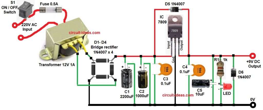
In this article AC mains supply goes to transformer and transformer reduces voltage to 12V AC.

Diodes D1 to D4 make bridge rectifier and this bridge rectifier changes AC to DC.

Capacitor C1 smooths DC and removes ripple and this smooth DC goes to 7809 IC input.

IC 7809 gives fixed 9V DC output.

Capacitors C3 and C4 reduce noise and LED with 1k resistor shows power ON.

Diode D5 protects 7809 when power is OFF and diode D6 protects circuit from reverse connection.

Fuse saves circuit from overload and ON/OFF switch controls main power.

Conclusion:

In this project, Regulated 9V Power Supply Circuit using IC 7809 is made and tested.

The circuit gives stable 9V output and it works properly.

IC 7809 makes the circuit easy and reliable.

This power supply is useful for many electronic circuits.

It is good for learning basic power supply concept.

References:

Powering a 12V and a 9V device from single power supply with LM7809 voltage regulator

Filed Under: Power Supply Circuits

About Admin-Lavi

Lavi is a B.Tech electronics engineer with a passion for designing new electronic circuits. Do you have questions regarding the circuit diagrams presented on this blog? Feel free to comment and solve your queries with quick replies

Previous Post: « 5 To 20 Minutes Alarm Timer Circuit
Next Post: Transformer Based 12V DC 3A Power Supply Circuit »

Reader Interactions

Leave a Reply Cancel reply

Your email address will not be published. Required fields are marked *

Primary Sidebar


Categories

  • Alarm Circuits (45)
  • Amplifier Circuits (67)
  • Arduino Projects (99)
  • Audio Circuits (114)
  • Automobile Circuits (19)
  • Battery Charger Circuits (65)
  • Free Energy (13)
  • Heater and Temperature Controllers (13)
  • High Voltage (1)
  • Indicator Circuits (45)
  • Inverter Circuits (20)
  • IoT projects (1)
  • LDR Circuits (26)
  • LED and Lamps (148)
  • Meters and Testers (30)
  • Motor Controllers (22)
  • Oscillator Circuits (39)
  • Power Supply Circuits (104)
  • Remote Control Circuits (10)
  • Security and Protection (29)
  • Sensors and Detectors (126)
  • Solar Circuits (29)
  • Timer Circuits (41)
  • Transistor Circuits (87)
  • Transmitter Circuit (17)
  • Tutorials (8)
  • Water Level Controller (6)

Recent Posts

  • 12V Battery Low Voltage Alarm Circuit
  • Low Voltage Alert Circuit for 9V Battery
  • Digital Code Lock Circuit using IC 4017
  • Darkness Activated LED Circuit
  • Fan Start 10 Second Delay Timer Circuit

Recent Comments

  1. TDHofstetter on DIY Variable Power Supply Circuit using Arduino
  2. feathbuff on Simple Micro Ampere Meter Circuit
  3. Admin-Lavi on Simple School Project Multimeter Circuit
  4. choke on Simple School Project Multimeter Circuit
  5. Admin-Lavi on Analog to Digital Converter Circuit using IC 555

Copyright © 2026 | New Circuit Ideas