This 100 Watt Inverter Circuit using IC 4047 which gives 100 watt power.
It uses one small chip called IC 4047 and this chip help to change DC power from battery to AC power.
We can use this inverter for small things like light, fan or charger.
It is easy to make and good for learning.
How the Circuit Works:
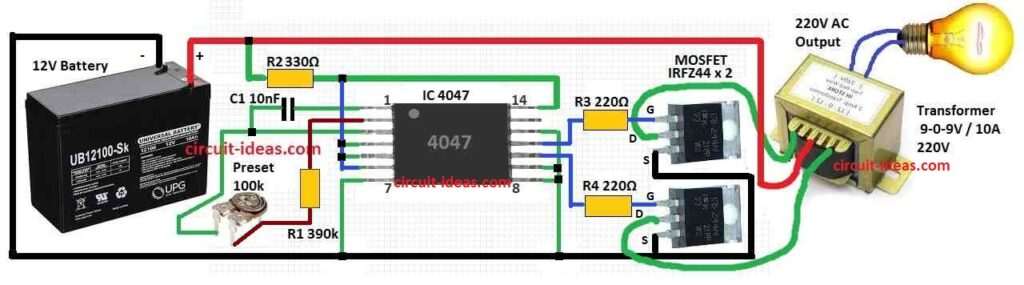
Parts List:
| Category | Component | Quantity |
|---|---|---|
| Resistors | 390k 1/4W CFR | 1 |
| 330Ω 1/4W CFR | 1 | |
| 220Ω 1/4W CFR | 2 | |
| 100k Preset | 1 | |
| Capacitor | PPC 10nF Capacitor | 1 |
| Semiconductors | IC 4047 | 1 |
| IRFZ44 MOSFET | 2 | |
| Transformer as per diagram | 1 | |
| 12V Battery | 1 |
This 100 watt inverter uses IC 4047 to work.
IC 4047 is main part in this circuit and it works like astable multivibrator.
This setting make pulses come out from pin 10 and pin 11 one after other.
How fast pulses come can change using VR1 (potentiometer) and C1 (capacitor).
Mosfet drain pins go to transformer secondary coil and its source pins connects to battery negative.
When pulses come from pin 10 and 11 they turn ON Mosfets one by one.
These Mosfets are very important for this circuit.
When Mosfets turn ON they send power to transformer coil.
This make magnetic field in transformer go up and down.
Because of this magnetic field transformer give AC voltage around 220V on output side.
So IC 4047 make pulses → pulses turn on Mosfets → Mosfets power transformer → transformer give AC power.
We can change output voltage by adjusting VR1 and C1.
This circuit is simple and useful and it changes DC from battery to AC which we can use for many devices and machines.
Formulas:
Below some important formula for making circuit like this:
Transformer Turns Ratio:
Transformer output voltage depend on turns ratio.
The ratio of input voltage (Vi) to output voltage (Vo) is same like ratio of secondary turns (Ns) to primary turns (Np).
Formula:
Ns / Np = Vo / Vi
where:
- Ns is the number of turns in secondary coil which gives big voltage
- Np is the number of turns in primary coil which takes small input voltage
- Vo is the output voltage from transformer AC which is high
- Vi is the input voltage to transformer DC which is low
Transformer work using electromagnetic induction.
When current connects to primary coil it make magnetic field.
This field then connects to secondary coil and make voltage there.
How many turns in each coil changes and how strong field is and how much voltage we get.
How the Formula Work:
More Turns → More Voltage:
If secondary coil (Ns) have more turns than primary coil (Np then output voltage (Vo) is more than input voltage (Vi).
Because more turns in secondary = stronger magnetic field = more voltage.
Less Turns → Less Voltage:
If secondary coil have less turns than primary then output voltage is small.
Less turns = weak magnetic field = less voltage.
Note:
So how much voltage go up or down depend on ratio between Ns and Np.
By using this formula we can guess output voltage but we know input voltage and how many turns are there in transformer coil.
How to Build:
The following steps are used in building a 100 Watt Inverter Circuit using IC 4047.
- Take 12V battery and connect positive (+) wire to the circuit.
- Connect negative (–) wire to the Mosfets source pins.
- Put IC 4047 in socket and be careful to place in the correct direction.
- Connect potentiometer VR1 between pin 6 and 7 of IC 4047.
- Connect capacitor C1 from pin 6 to ground (negative line) of circuit.
- Connect drain pins of Mosfets to secondary coil of transformer.
- Source pins of Mosfets connects to battery negative (–).
- Connect primary coil of transformer to pin 10 and 11 of IC 4047 which are the output pins.
- Connect secondary coil to Mosfet drain pins.
- Add resistors and other parts as shown in full circuit diagram.
- Use breadboard or PCB to arrange parts and check all wires are clean and are not touching the wrong pins.
- Solder carefully to make strong connection with no loose wires.
Testing the Circuit:
- Turn ON circuit by connecting 12V battery.
- Use multimeter to check output voltage at transformers secondary coil.
Adjusting:
- Turn VR1 potentiometer to change pulse speed and check how output voltage changes.
- To get full 220V AC maybe we need to change or upgrade some parts in our circuit.
Safety Tips:
- Always be careful while working with electric circuits.
- Read datasheet of IC 4047 and other parts to know details.
- Before turning ON check all connections again to be sure there is no mistake.
Conclusion:
Inverter are small but strong device as it connects DC power and AC power together.
This 100 Watt Inverter Circuit using IC 4047 is a cheap and useful for many works.
People who love electronics and new designers can make their own inverter.
These inverters can be used for small projects or big power work.
Just we need to understand basics and follow correct steps while making.