Battery status circuit is very useful in electronics systems.
It helps keep battery healthy and working good in devices.
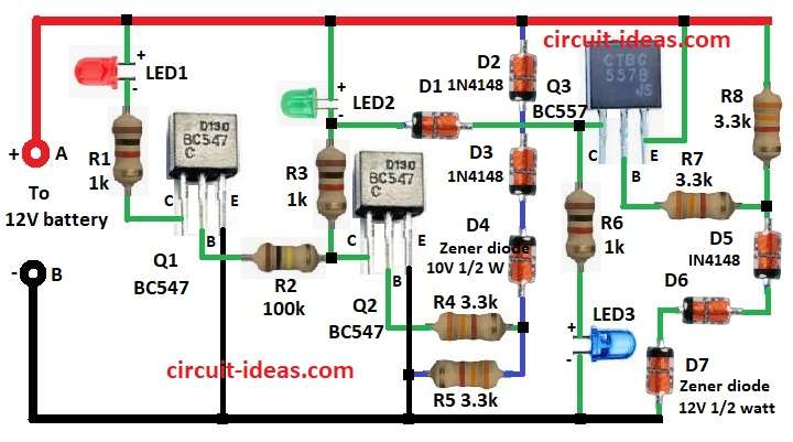
3 LEDs Battery Status Indicator Circuit is simple but works well and it shows battery voltage using three lights.
Each LED shows different voltage.
We can see if battery is low, normal or full just by looking.
Circuit Working:
Parts List:
| Component | Specification | Quantity |
|---|---|---|
| Resistors (All resistors are 1/4 watt unless specified) | 1k | 3 |
| 3.3k | 4 | |
| 100k | 1 | |
| Semiconductors | Transistors BC547 | 2 |
| Transistor BC557 | 1 | |
| LEDs Red, Green and Blue 5mm 20mA | 1 each | |
| Diodes 1N4148 | 5 | |
| Zener Diodes 10V 1/2 watt | 1 | |
| Zener Diodes 12V 1/2 watt | 1 |
This circuit uses simple parts like transistors, resistors, diodes and Zener diodes.
LEDs show battery status.
If battery goes below 10V then Zener diode D4 10V works.
It lets current pass and turns ON the transistor Q2 and LED1 lights.
This means battery is low.
If battery is between 10V and 12V then D6 works but D7 12V does not works yet.
Q3 turns ON and LED2 lights.
This means battery is normal.
If battery over 12V then D7 starts working.
It turns OFF Q3 then turns ON Q1 and LED3 lights.
This means battery is full.
Note: Connect battery between point A and B.
Formulas with Calculations:
Formulas for 3 LED Battery Indicator:
1. Base Resistor:
To make transistor work right find base current:
Iᵢ = Iₚ / hFE
where,
- Iₚ is the collector current
- hFE is the transistor gain
Example:
If Iₚ = 10mA and hFE = 100:
Iᵢ = 10mA / 100 = 0.1mA
Now find base resistor:
Rᵢ = (Vₑ – Vₒₗ) / Iᵢ
where,
- Vₑ is the input voltage
- Vₒₗ is the base to emitter voltage for 0.7V
2. LED Resistors:
To protect LED use formula:
R = (Vₑ – Vₚ) / Iₑ
where,
- Vₑ is the power supply
- Vₚ is the LED forward voltage
- Iₑ is the LED current from 10 to 20mA
How to Build:
To build a 3 LEDs Battery Status Indicator Circuit follow the below mentioned steps for connections:
- Take all parts shown in circuit diagram above.
- Connect collector of Q1 to +V through LED1 and R1.
- Connect base of Q1 to collector of Q2 through R2.
- Connect emitter of Q1 to GND.
- Connect collector of Q2 to +V through LED2 and R3.
- Connect base of Q2 to one side of R4 and other side of R4 goes between D4 and R5.
- Connect emitter of Q2 to GND.
- Connect D2, D3, D4 from +V and then to one side of R5 and other side of R5 to GND.
- Connect collector of Q3 between LED2 and R3.
- Also connect R6 and LED3 in series from Q3 collector to GND.
- Connect emitter of Q3 to +V.
- Connect base of Q3 to R7.
- Connect R8 from +V to D5, D6, D7 in series and then to GND.
Conclusion:
This 3 LEDs Battery Status Indicator Circuit is easy way to see battery level.
It uses Zener diodes and transistors to show if battery is low, okay or full.
It is a good project for electronics lovers to learn about simple parts and circuits.