This article teaches, how to make 500 Watt Inverter Circuit that work good by using one smart chip name IR2153.
This chip help to change 12V car battery to 230V like home electricity, as this chip is better than old one because:
Thus, the inverter work more strong and does not break easily, so to make this 500 watt inverter we need the following parts:
- One special transformer
- Strong transistors must use metal piece like heat sink to keep them cool
- Power from 9V to 14V like car battery
- One fuse for safety
Also, we can change inverter setting to use less power when there is no work and if we live in place with different electric system then we can change output from 50Hz to 60Hz also.
What transistors we use depend how much power we want from inverter, thus this post show many option for that.
Important: This inverter does not give smooth home power like normal electricity.
What is a 500 Watt Inverter Circuit:
A 500 Watt inverter circuit is one electronic circuit that change DC power from battery or other source into AC power, as AC power usually uses 120V or 230V.
When only DC power is there like in car system, off-grid place or when power go out inverter help give AC power.
Hence, we can use machines or tools that need AC to work.
Circuit Diagram:
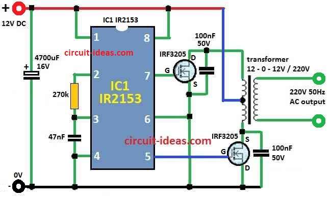
Parts List:
| Components | Values | Quantity |
|---|---|---|
| Resistors | ||
| 270k 1/4 watt | 1 | |
| Capacitors | ||
| PPC 47nF | 1 | |
| PPC 100nF 50V | 2 | |
| Electrolytic 4700µF 16V | 1 | |
| Semiconductors | ||
| MOSFETs IRF3205 | 2 | |
| IC IR2153 | 1 | |
| Transformer 12-0-12V / 42 Amp / 220V | 1 | |
| Battery 12V / 500 Ah | 1 |
How to Build:
These steps will help us to build the 500 Watt Inverter Circuit:
First, choose 12V transformer with two secondary wires and it must handle full load.
Next, pick big enough heat sink for power transistors which depend on how much load we will use.
For safety also use isolation pad or keep heat sinks far so they do not touch each other or ground.
Hence, use good power source between 9V to 14V.
Also, add one fuse in power line for extra safety.
If we do not need exact 50Hz, then we can try other frequencies, for example 100Hz to 300Hz.
Then we can change frequency by changing value of Rx and Cx parts.
Pick following MOSFETs based on how much power we need:
IRF3205 for up to 600W
IRFZ44 for up to 200W
IRFZ48 for up to 350W
If load is more than 600W we can join many IRF3205 together in parallel.
But be very careful this inverter give dangerous high voltage which can hurt or kill.
Remember, do this only at ones own risk and writer is not responsible if anything goes wrong.
Formulas:
Below are some formulas for making 500 Watt Inverter Circuit:
Further, when frequency is important we use IC IR2153 and this IC uses parts outside resistor and capacitor to set the frequency.
Formula is:
fosc = 1 / (0.693 × Rosc × Cosc)
where:
- fosc is the frequency
- Rosc is the resistor for oscillator
- Cosc is the capacitor for oscillator
2. Dead Time Control:
Dead time stop both transistors from turning ON at same time and this save parts from damage and IC IR2153 has system for that.
Formula is:
tdead = Rdead × Cdead
where:
- tdead = dead time
- Rdead is the resistor for dead time
- Cdead is the capacitor for dead time
Safety Rules:
Always follow safety rules when working with 500 watt inverter and even if input is low voltage output is very dangerous.
Also, if we touch both output wires at same time it can hurt like real home electricity even if it not connect to ground.
Do everything at ones own risk and writer is not responsible if something bad happens.
Conclusion:
Finally, to make 500 Watt Inverter Circuit we must know good about power and electronics, also we must be careful because high voltage is risky.
Hence, for normal use many inverters are already available in market, so people can buy best one depending on what they need.
Leave a Reply