An Simple AC Mains Presence Indicator Circuit helps us check whether AC mains supply is present at the input and whether power reaches the load side.
This circuit is easy, low-cost and very useful for home appliances, control panels, extension boards and industrial systems.
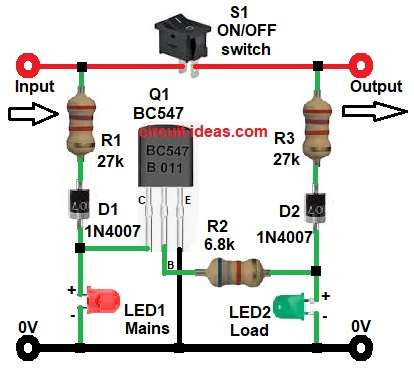
In this circuit, two LEDs show two different conditions, first LED1 indicates that mains power is available at the input side and next, LED2 indicates that power reaches the load or output side.
Therefore, the user can quickly know whether the switch is ON or OFF and whether supply is available.
Since this circuit works directly on 230V AC mains, safety is the most important part, a small mistake can cause electric shock, fire or component damage.
Circuit Working:
Parts List:
| Components | Values | Quantity |
|---|---|---|
| Resistors | 27k 1/4 watt | 2 |
| 6.8k 1/4 watt | 1 | |
| Semiconductors | Transistor BC547 | 1 |
| LED standard 3 mm or 5 mm | 2 | |
| Diodes 1N4007 | 2 | |
| ON/OFF SPST Switch | 1 | |
| Power supply Input / Output / GND terminals | As required |
The circuit starts with AC input enters the input terminal and when this AC mains comes to the input, current flows through resistor R1 and diode D1, then LED1 glows and it shows that mains power is available.
Now, when switch S1 remains open the output side does not get supply and as a result, LED2 stays OFF because no current reaches the load side.
Next, when switch S1 closes the AC supply then moves from input to output and then the current flows through resistor R3 and diode D2, after that LED2 glows and shows that output power is available for the load.
Meanwhile, transistor Q1 BC547 helps in switching and proper indication and resistor R2 gives base current control to transistor Q1, because of this, the transistor operates safely and improves LED indication performance.
So, in simple words:
- LED1 means mains is available.
- LED2 means load side is active.
How to Build:
To build a Simple AC Mains Presence Indicator Circuit following are the steps required for connections:
- First, start the circuit by collecting all the components as shown in diagram above.
- Next, start with input side and connect AC phase line to input terminal.
- And connect neutral line to ground terminal.
- Then take resistor R1 with one end of resistor goes to input phase and other end goes to diode D1 anode.
- Then take diode D1 with anode end connects to R1 and cathode end connects to LED1 and Q1 transistor collector line.
- LED1 mains indicator anode connects after D1 and cathode connects to ground terminal.
- Next, take switch S1 and connect one terminal to input line and connect second terminal to output line.
- After that, take output side from right side terminal and connect this to load.
- Then take resistor R3 and one end connects to output line and other end connects to diode D2.
- Diode D2 anode end connects to R3 and cathode end connects to LED2 and resistor R2 node.
- LED2 load indicator anode end connects after D2 and cathode end connects to ground.
- Next, take transistor BC547 Q1 with collector pin connects between LED1 anode side and diode D1 cathode side.
- Base pin between cathode of diode D1 and anode of LED2 through resistor R2.
- And finally, emitter pin connects to ground.
Safety Note:
This circuit operates directly on 230V AC mains supply, handle with extreme care.
Always switch OFF power before testing or construction.
Use proper resistor wattage, insulated enclosure and input fuse to avoid electric shock and fire hazards.
Conclusion:
To conclude, this Simple AC Mains Presence Indicator Circuit gives a simple and effective way to monitor mains supply and output load condition.
First, LED1 shows input AC presence and LED2 shows output load supply status.
Moreover, the BC547 transistor improves switching action and indication clarity.
Therefore, this circuit works well for domestic and industrial applications and also, it uses easily available components so anyone can build it without difficulty.
Leave a Reply