Acupuncture Point Locator Circuit is small device which helps to find special point on human body.
In acupuncture thin needle goes inside our body part to reduce pain.
This is old medical method.
These special body points called acupuncture point or just acupoints.
People think energy move through body using these points.
To find these point this circuit uses electronic things.
One way is to check skin resistance.
Skin resistance on acupuncture point is usually low than other skin part.
This circuit have sensor touch to our skin with one part to catch signal and light and sound comes ON when point is found.
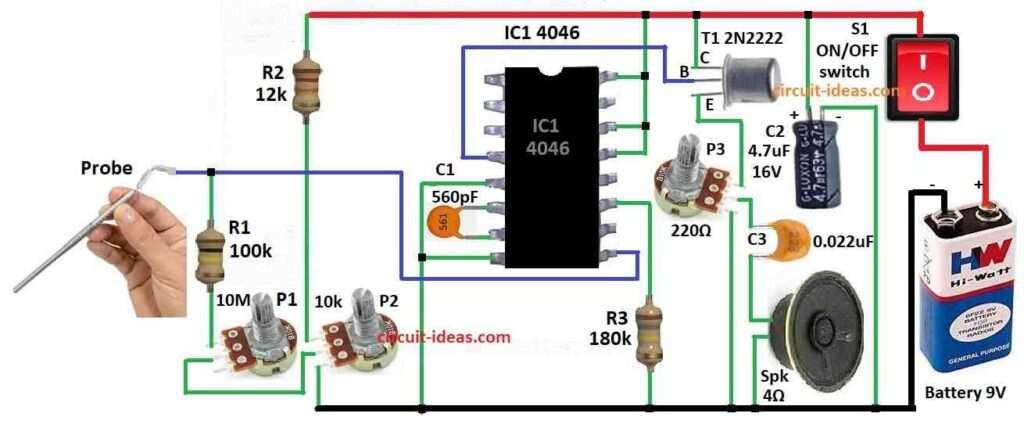
Circuit Working:
Parts List:
| Category | Description | Quantity |
|---|---|---|
| Resistors | ||
| 100k 1/4 watt | 1 | |
| 12k 1/4 watt | 1 | |
| 180k 1/4 watt | 1 | |
| Potentiometer 10M | 1 | |
| Potentiometer 10k | 1 | |
| Potentiometer 220Ω | 1 | |
| Capacitors | ||
| Ceramic 560pF | 1 | |
| Ceramic 0.022μF | 1 | |
| Electrolytic 4.7μF 16V | 1 | |
| Semiconductors | ||
| Transistor 2N2222 | 1 | |
| IC 4046 | 1 | |
| ON/OFF Switch | 1 | |
| Speaker 4Ω | 1 | |
| Battery 9V | 1 | |
| Probe (Medical) | 1 |
For this the acupuncture point locator uses one electronic circuit.
It uses one chip called CD4046 and this chip is CMOS type and have VCO voltage control oscillator inside.
Parts R3 and C1 control how fast the VCO work with its frequency.
This changes more when control voltage change.
Skin resistance R1 and one adjustable part P1 make control voltage using voltage divider.
When skin resistance goes low the control voltage and frequency goes high.
This make sound come from speaker.
Transistor T1 gives enough power to speaker so it can work.
Formula:
PLL IC like 4046 is useful in many things like FM radio circuit and making frequencies.
Acupuncture Point Finder is also used IC 4046 in special way.
It help to find change in skin resistance or impedance at acupuncture point.
Main work of this finder is to check frequency from VCO and this frequency changes when skin resistance changes at point.
The formula is:
fout = f0 + k × R
where:
- fout is output frequency of VCO
- f0 is base frequency of VCO
- k is one fixed value from circuit
- R is skin resistance
One example:
Assemble:
Electrodes touch acupuncture point with probe.
Use frequency counter to see VCO output.
Understand:
If fout changes it means skin resistance change and that show acupuncture point is found.
This IC 4046 is good because it can change with skin signal and help to build acupuncture finder easily.
How to Build:
To build a Acupuncture Point Locator Circuit following steps are needed for connection:
- Put CD 4046 IC on breadboard.
- Connect pin 5 and 8 of CD4046 to ground GND.
- Connect pin 13, 14 and 16 to positive power VCC.
- Connect pin 6 and 7 with 560pF capacitor.
- Connect pin 4 to base of transistor 2N2222.
- Connect emitter of 2N2222 to speaker using one potentiometer.
- Put one 4.7μF capacitor between positive and ground and across supply.
- Connect 2 potentiometer in series between probe and positive wire.
Testing:
- Turn ON the circuit.
- Move potentiometer P1 slowly.
- When speaker make sound it mean circuit is working.
- Sound will change when skin resistance change.
- Adjust P1 and P2 to test on different skin points and listen to sound frequency go up or down.
Note:
- These steps are simple version but for more full information please check parts datasheet.
- Be safe with circuits and double check all wires before power ON because wrong wire can break parts.
Conclusion:
Electronic Acupuncture Point Locator Circuit finder is good tool.
But it cannot be replaced with real acupuncturist.
Acupuncture is difficult medical work.
How well it works depend on patient need and doctors skill.
Leave a Reply