To begin with, this project is for Bench Power Supply Circuit which is easy to use and works good and we can change voltage and see current.
What is a Bench Power Supply:
Bench power supply circuit is useful device which gives steady and control power for working in lab, workshop and testing electronics.
Also, this circuits main job is to give same voltage and current to circuits and devices when building, checking or fixing them.
Circuit Working:
Parts List:
| Components | Values | Quantity |
|---|---|---|
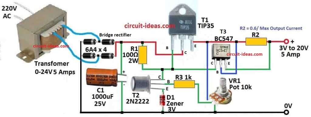
| Resistors | 100Ω 2W | 1 |
| 1k | 1 | |
| R2 (calculated as 0.6 / max output current) | 1 | |
| Potentiometer 10k | 1 | |
| Capacitor | Electrolytic 1000µF 25V | 1 |
| Semiconductors | Transistors 2N2222, TIP35, BC547 | 1 each |
| Bridge diodes 6A4 | 4 | |
| Transformer 0-24V 5 Amps | 1 |
Next, the potentiometer adjusts the feedback, so the output voltage changes as needed.
Additionally, the Zener diode sits between the emitter and ground of the 2N2222 to stabilize the voltage, and a resistor in the TIP35 emitter line limits the current.
Also, TIP35 transistor is uses like emitter follower and its base connects straight to 30V input.
Moreover, one 2N2222 transistor and one potentiometer makes feedback loop and TIP35 emitter connects to base of 2N2222.
Next, the potentiometer adjusts the feedback, so the output voltage changes as needed.
Additionally, the Zener diode sits between the emitter and ground of the 2N2222 to keep the voltage stable and a resistor in the TIP35 emitter line limits the current.
After that, BC547 transistor also connect with this resistor and TIP35 base and if too much current connect to load then BC547 stop it and acts like current limiter.
So 2N2222 and potentiometer controls the voltage and BC547 controls the current and protect from overload.
Formulas and Calculations:
This design control the base voltage of transistor T1 and its control output voltage too and it does this by changing voltage drop on resistor R1 and this drop happen mostly from current made by transistor T2.
Also, potentiometer VR1 connects one end to ground, so when slider connects close to ground side then base current of T1 makes voltage drop on R1 and this turns OFF T2.
Output voltage at emitter of T1 is almost same as collector voltage with only little less:
VE = Vin – 0.7V
0.7V is normal drop between base and emitter of BJT like T1
So if input is 15V:
VE = 15 – 0.7 = 14.3V
Now when VR1 slider moves to high side of positive then T2 gets full emitter voltage from T1 and turns ON strong.
Then, the Zener diode D1 connects directly with resistor R1, for example, if the Zener voltage is Vz, the base voltage of T1 becomes approximately equal to Vz.
So:
VE = Vz – 0.7V
Example: if Zener D1 is 6V then:
VE = 6 – 0.7 = 5.3V
This mean Zener voltage set the lowest output voltage when VR1 is at lowest point and this method is simple and works good, but it is having one big problem it does not protect from short circuit.
Also, if the output accidentally shorts or the current becomes too high, the T1 transistor heats up quickly and may burn, so however, we can fix this problem easily by adding current control.
How to Build:
To build a Bench Power Supply Circuit follow the below steps:
Power Supply Section:
- First, connect transformer wires secondary side to bridge rectifier input.
- Then connect output of rectifier to one big filter capacitor to smooth the DC.
TIP35 Transistor:
- Next, connect emitter of TIP35 to positive power line, collector of TIP35 connects to the load like resistor or circuit and base of TIP35 connect direct to 30V input.
Feedback Loop:
- After that, emitter of 2N2222 transistor connect to TIP35 output.
- Now base of 2N2222 connect to point between potentiometer and resistor and other end of resistor connects to emitter of TIP35.
- Then collector of 2N2222 connects to positive power line.
- And Zener diode connect between emitter and ground of 2N2222.
Current Limiting Section:
- Also, put one resistor in line with TIP35 emitter for current limit.
- Next, base of BC547 transistor connect to point between this resistor and TIP35 emitter.
- Collector of BC547 connects to positive power and emitter of BC547 connect to TIP35 base.
Control:
- Then middle pin wiper of potentiometer connects to base of 2N2222 transistor.
- Also, one end of potentiometer connect to positive line and turn potentiometer to adjust feedback and control output voltage.
Load Connection:
- Connect the load which is the resistor or circuit to TIP35 collector.
Heat Sink:
- TIP35 can get hot so use heat sink to keep it cool.
Extra Tips:
- Always check connections two times and be sure positive and negative are correct.
- Use right resistor values for good feedback and current limit.
- We can add small capacitors or diodes for better stability and safety.
- Connect ground of circuit to ground of power supply.
Note:
- After building slowly turn potentiometer and check voltage change.
- Also test current limit by changing load.
- Be sure parts do not go over their max voltage or current rating.
Conclusion:
Overall, in this post BC547 stops too much current as it works like a safety switch.
Hence, potentiometer with 2N2222 controls how much voltage comes out and together we can make Bench Power Supply Circuit that can adjust voltage and stop too much current.
Leave a Reply