To change 3V to 5V we need to use a boost converter, as this Simple Boost Converter Circuit from 3V to 5V take low voltage and make it higher.
Also, it takes 3V from battery and give 5V to run our devices.
Circuit Working:
Parts List:
| Components | Values | Quantity |
|---|---|---|
| Resistors (All resistors are 1/4 watt unless specified) | 3.9k | 1 |
| 560Ω | 1 | |
| 2.2k | 1 | |
| Capacitors | Electrolytic 100µF 25V | 1 |
| Semiconductors | Transistor BC338 | 1 |
| Transistor BC547 | 1 | |
| Diode 1N4148 | 1 | |
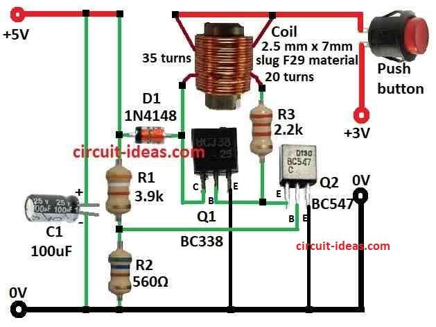
| Coil 2.5mm x 7mm slug F29 material 35 turns, 20 turns | 1 | |
| Push button | 1 |
This article show how to make 3V to 5V boost converter, which take 3V input and give 5V output, also it work by using transistor Q1 BC338 to switch battery current and store energy in inductor.
When transistor is OFF inductor make high voltage and diode 1N4148 pass this voltage and capacitor smooth it to get steady 5V.
Furthermore, resistors 3.9k and 560 ohm make voltage divider to set reference voltage.
Formulas:
When making boost converter for 3V to 5V, some important calculations and things to we need to think about.
1. Find Duty Cycle D:
D = Vout / Vin
In this circuit:
D = 5V / 3V = 1.67
2. Find Inductor Value L:
Use formula:
L ≥ (Vout − Vin) * Vout / (f * ΔI)
where:
- Vin is 3V for input
- Vout is 5V for output
- f is the switching frequency
- ΔI is the inductor ripple current for 20 to 40% of output current
Note:
Choose the inductor, diode, transistor, and capacitor carefully to achieve stable and efficient voltage boosting; moreover, the exact component values depend on the selected parts and the circuit requirements.
Also, test and try to get good result.
How to Build:
To build a Simple Boost Converter Circuit from 3V to 5V below are steps for connection:
- First, transistor Q1 collector goes to one side of inductor and other side of inductor goes to diode D1 1N4148 anode.
- Then capacitor C1 100uF positive side goes to +5V output and negative side of C1 goes to ground.
- After that, Q1 base connect through resistor R3 and coil.
- Now Q2 emitter goes to ground, Q2 base connect to voltage divider with resistors R1 and R2 and Q2 collector goes to R3 and coil.
- Next, top end voltage divider goes to +5V and bottom of voltage divider goes to ground.
- Also, push button connect to +3V supply.
Note:
- Check all wiring carefully and be careful when using electric parts.
Conclusion:
Overall, this Simple Boost Converter Circuit change 3V to 5V, it uses few parts like transistor, inductor, diode and capacitor.
Also, this circuit is good for small projects and is easy to make if we know basic electronics, but always check all the circuit parts connection and stay safe.
Leave a Reply