No button needed as this circuit uses a smart chip known as TTP223 to feel our touch.
Like magic it touches the pad and it turns ON or OFF
This Simple Capacitive Touch Switch Circuit using IC TTP223 is an easy way to make a touch switch for fun or projects.
Circuit Working:
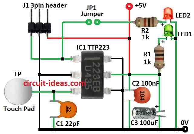
Parts List:
| Component | Description | Quantity |
|---|---|---|
| Resistors | ||
| 1k 1/4 W | 2 | |
| Capacitors | ||
| Ceramic 22pF | 1 | |
| Ceramic 100nF | 1 | |
| Electrolytic 100µF 25V | 1 | |
| Semiconductors | ||
| IC TTP223 | 1 | |
| LED 5mm green | 1 | |
| LED 5mm red | 1 | |
| Jumper | 1 | |
| 3 pin header | 1 | |
| Touch pad | 1 |
This is a basic touch switch circuit for electronics hobby people.
Even though it uses SMD parts it is easy to make on an SMD board.
Main part is a small ₹20 chip called TTP223 in BA6 package.
TTP223 is a touch sensor IC which works like a button but we just touch a pad.
It uses low power and works with DC or AC.
We can connect it to any microcontroller using 3 pin header J1.
Use 5V for power when we touch pad TP and output pin OUT goes high.
Green LED1 shows power is ON and Red LED2 shows output status as optional.
To use LED2 close the solder jumper JP1.
A test version was made on normal board using regular parts.
TTP223 was on SMD to DIP adapter with small 10mm x 10mm copper board used as touch pad.
If we build this way keep wire from pad to pin 1 of TTP223 very short.
Some modules use 1k resistor between pad and pin 3 of TTP223 but not tested yet.
Touch pad size and wire length affect sensitivity.
To increase sensitivity use bigger or thinner touch pad and adjust for our use.
How to Build:
To build a Simple Capacitive Touch Switch Circuit using IC TTP223 follow the below mentioned connections steps:
Prepare the SMD Board:
- Cut board to right size with big enough for parts and wires.
Mount TTP223 IC:
- Solder TTP223 chip on board and check datasheet for chip direction.
Connect Parts:
- Solder 3 pin header J1 on board and ensure pin direction is right.
- Solder green LED for power.
- Solder red LED for output if needed.
- If using 1k resistor between touch pad and pin 3 then solder it.
Add Touch Pad:
- Cut small copper board with about 10mm x 10mm.
- Solder wire from pad to pin 3 of TTP223.
Final Wiring:
- Connect VCC and GND to power.
- Connect OUT pin to microcontroller or other circuit.
Use Output LED (Optional):
- To use red LED for output, bridge jumper JP1.
Test Circuit:
- Power the board.
- Touch the copper pad.
- Green LED should turn ON (power).
- Red LED shows output if connected.
Adjust Sensitivity:
- If needed change pad size or thickness.
- Bigger or thinner pad is more sensitive.
Mount Everything:
- Put circuit in a box or fix it on a surface.
Note:
- This is basic guide and check TTP223 datasheet for full details.
Conclusion:
This Simple Capacitive Touch Switch Circuit using IC TTP223 is simple and cheap.
It is good for hobby or DIY use.
This circuit is easy to make with no button needed.
Leave a Reply