Think about a Simple Colpitts Oscillator Circuit like small kid on swing.
Inductor and capacitor like swing are set as they make swing go back and forth.
But swing can slow down.
For that transistor come for help.
It is like friend push a kid and keep swing move nice and steady.
Same way Colpitts oscillator keep wave go ON and ON not stop.
Circuit Working:
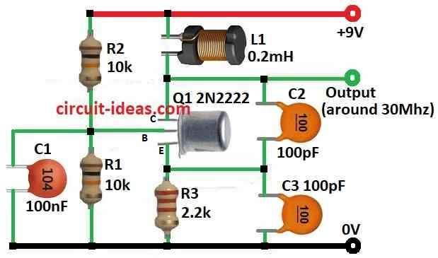
Parts List:
| Category | Item | Quantity |
|---|---|---|
| Resistors | 10k 1/4 watt | 2 |
| 2.2k 1/4 watt | 1 | |
| Capacitors | Ceramic 100nF | 1 |
| Ceramic 100pF | 2 | |
| Semiconductors | Transistor 2N2222 | 1 |
| Coil inductor 0.2mH | 1 |
In this post we can learn how LC oscillator work and also to build one type of Colpitts oscillator.
Oscillators are very important in electronics so we see them in clocks, radios and computers.
They make wave signals and different types are RC, LC and crystal where each one is good for different work.
There is no best oscillator but which one to use depend on our circuit.
Capacitor and inductor L and C make wave and capacitor charges and give energy to inductor.
Inductor give it back in opposite way and this go on and on by making oscillation.
But wave die slowly because of resistance.
To keep wave going we use amplifier and feedback and this feedback give lost energy back and this make steady sine wave.
Colpitts oscillator can make signal like 30 MHz.
For LC oscillator with transistor two things important feedback must be in same phase and strong enough to cover energy loss.
Q is quality factor and it show how good the circuit keep wave and big Q mean better.
Quartz crystal has very high Q which is much better than LC circuit.
Formulas:
Colpitts Oscillator Frequency Formula:
This formula tell how to find Colpitts oscillator frequency (f):
f = 1 / (2 * π * √(L * Ceq))
where:
- f is frequency in hertz Hz.
- L is inductor value in henry H.
- Ceq is capacitor equivalent value in farad F.
How to Find Ceq Equivalent Capacitance:
In circuit capacitor C2 and C3 are connected in series so we calculate Ceq like this:
1/Ceq = 1/C2 + 1/C3
Important Note:
This formula give simple idea of oscillator frequency.
But in actual circuit exact frequency can change because of many things like small error in components, extra small capacitance from wires and behavior of transistor.
How to Build:
To build a Simple Colpitts Oscillator Circuit we need to follow the below mentioned steps:
Connect the Components:
- Put all parts together like in the circuit diagram.
- Be careful with capacitor direction polarity and how inductor is placed if it not same both sides.
Bias the Transistor:
- Use resistor R1 to give bias to transistor.
- This make sure transistor work in active mode not cutoff or saturation.
Apply Power:
- Connect power supply.
- Positive wire connects to Vcc and negative wire to ground.
Adjustment:
- If required we need to change capacitor and inductor values to get correct frequency.
- Try different values and tune it little bit.
- After all parts are connected turn ON the power.
- Use oscilloscope or frequency counter to see the output signal.
- If result is not good then change values and test again until it works well.
Note:
- Making oscillator need some knowledge of electronics.
- Be sure we understand how it work before trying.
- Be safe when working with circuits and power.
Conclusion:
Simple Colpitts oscillator circuit is basic LC circuit.
It make stable sine wave signal.
It use capacitors and inductor for feedback and one amplifier to keep oscillation going.
By changing parts in feedback for capacitors and inductor, we can set the frequency we want.
Leave a Reply