Did anybody’s device ever had no battery but have other batteries with just wrong size?
This post show how to make a Dual Battery Charging Circuit.
It uses one power to charge two batteries.
It uses one small chip called IC 555 and other small things to ensure both battery get same charge.
If we want to use this device more then maybe this circuit will helpful.
What is a Dual Battery Charging Circuit:
Circuit for charging two batteries at same time called dual battery charging circuit.
This type of circuit is used in many times when two batteries need charge safe and separate.
Things like small electronic device, battery system and car stuff use this kind of circuit for many times.
Circuit Working:
Parts List:
| Type | Description | Quantity |
|---|---|---|
| Resistors (All resistors are 1/4 watt unless specified) | 33k | 2 |
| 8.2k | 2 | |
| 22k | 2 | |
| 15k | 2 | |
| 100k | 2 | |
| 470k | 2 | |
| 10k | 4 | |
| Presets 10k | 4 | |
| Variable Resistors Rx and Ry (to be calculated) | 1 each | |
| Semiconductors | Transistor BC547 | 2 |
| Diode 1N4007 | 2 | |
| Diode 15 Amp | 2 | |
| Zener Diode 14.4V | 2 | |
| IC 78L05 | 2 | |
| IC 555 | 2 | |
| Relay 12V | 2 | |
| SMPS charger for battery | 1 |
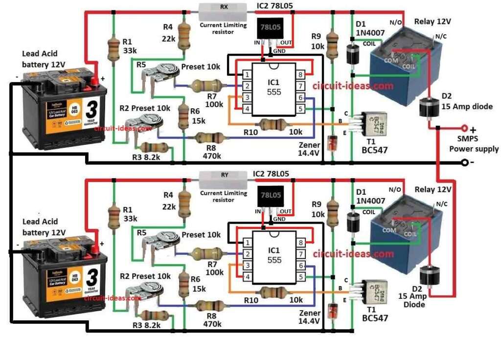
How twin battery charger circuit work is explained here below:
This circuit uses IC 555 two times like two same parts.
Each part control when battery start charge and when stop one for low and other one for high voltage.
SMPS give power to both IC 555 parts from same source.
It uses relays and diodes to send power to each battery.
Diodes are put between IC 555 and SMPS and they stop power from mix up between the two parts.
Relay take care of charging which work like switch.
When battery reach full level like high voltage then IC 555 tell relay stops charging.
When battery go down to low voltage then relay connect again and charging to start.
Resistors Rx and Ry control how much current go to each battery.
These resistors stop battery from overcharge or are not getting enough charge.
IC 555 set the rules for each battery charging.
When battery is full relay cut off the power and when battery is low its relay gives power again.
To find correct value for Rx and Ry we can use Ohms Law and check battery AH (ampere hour)
Resistors must be right to give safe and good charging.
Formulas and Calculations:
Formula for charging time show how long it take to full charge one battery using same current always:
Charging Time = Battery Ah / Charging Current
here:
- Charging time mean how many hours (h) will take to full charge battery.
- Battery Ah show how much power the battery can hold.
- Charging current is how much current in Amps A can charger give to battery.
How this formula work:
Battery capacity (Ah) tell how much electric power it can store.
Charging current (A) tell how fast battery gets charged.
To find how many hours are for full charge it will just divide battery Ah by charger current.
Example:
If battery is 50Ah and charger gives 5A then:
Charging Time = 50Ah / 5A = 10 hours
So battery will take 10 hours to full charge.
How to Build:
The below mentioned are the steps required for building a Dual Battery Charging Circuit:
- Make simple drawing of twin battery charger circuit.
- Put all parts like in circuit diagram and how they connect together.
- Find pin numbers for relay, diode, IC 555 and other parts.
- Look in datasheet to know correct pin layout.
- Connect IC 555 same as shown in circuit diagram.
- Put resistors Rx, Ry, diodes and other wires for each timer part.
- Connect SMPS to give power to both IC 555.
- Use diodes to send power to each IC 555 part.
- Relay is used to turn power ON / OFF to batteries.
- Rx and Ry control current to battery.
- Connect them properly.
- Use Ohms Law and battery Ah to find correct value.
- Use diodes D1 and D2 in two different places.
- This stop charging from mixing or disturb each other.
- Now connect wires to battery.
- Be sure positive and negative side are connected right.
- Before put parts on PCB and test circuit first.
- Fix problems now so there is no need fix later.
- Change IC 555 settings to correct battery charging level.
- Only change resistor value if really needed.
Follow Safety Rules:
- Be safe and check wire direction, insulate wires and avoid short circuit.
Final Test:
- After connecting to SMPS watch the charging.
- Ensure both batteries charging good and with no overcharge.
Conclusion:
When we make Dual Battery Charging Circuit then choose right parts for our battery type.
Always follow safety steps from battery company to stop damage or danger.
This help make charging safe and will work well.