Electromagnetic Telephone Ringer Circuit helps us know when call comes an when there is no need connect to phone line.
This circuit is useful when there is no access or do not want to touch phone line.
It works by sensing electromagnetic field from ringing signal and then buzzer turns ON.
The circuit can run with 9V battery.
But warning in some places making this circuit is not allowed by law.
Check all the rules before making it.
Circuit Working:
Parts List:
| Component | Specification | Quantity |
|---|---|---|
| Resistors (All resistors are 1/4 watt unless specified) | 470k, 12k, 1k | 1 each |
| 2.2k | 2 | |
| Capacitors | Ceramic 0.1µF | 1 |
| Electrolytic 1µF 25V | 1 | |
| Semiconductors | Transistor BC557 | 1 |
| Transistor BC547 | 3 | |
| LED 5mm, 20mA | 1 | |
| Air core coil make 50 close turns of 28 SWG enameled copper wire | 1 | |
| SPST switch | 1 | |
| Piezo buzzer | 1 | |
| 9V Battery | 1 |
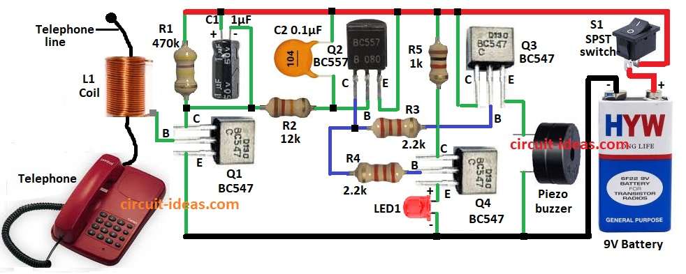
This circuit has coil sensor, some transistors, capacitors, resistors, piezo buzzer and 9V battery.
When phone rings AC signal makes electromagnetic field around coil L1.
Coil picks signal and transistor Q1 boosts it.
Q2 makes signal stronger again.
Then Q3 and Q4 work like switch and turns ON the buzzer.
When call comes LED1 lights and buzzer makes sound.
Circuit uses 9V battery and switch S1 to turn it ON or OFF.
Formulas with Calculations:
These are some formulas with example for simple telephone ringer circuit:
1. Voltage in Coil L1:
V = -N × (dΦ/dt)
where,
- V is the voltage
- N is the coil turns
- Φ is the magnetic flux change
Example:
N = 50, flux change = 0.002 Wb/s
V = -50 × 0.002 = -0.1V
2. Transistor Gain:
β = Ic / Ib
where,
- β is the gain
- Ic is the collector current
- Ib is the base current
Example:
Ic = 5mA, Ib = 50µA
β = 5mA / 50µA = 100
τ = R × C
where,
- τ is the time constant
- R is the resistor
- C is the capacitor
Example:
R = 1kΩ, C = 1µF
τ = 1k × 1µF = 1ms
How to Build:
To build a Electromagnetic Telephone Ringer Circuit following steps are needed to be followed:
- Fix all parts like shown in circuit diagram.
- Connect coil L1 to base of Q1 and L1 to one wire of phone line.
- Q1 collector goes to positive supply through resistor R1.
- Q1 emitter goes to GND.
- Q2 base connects to Q1 collector through R2.
- Capacitor C1 positive go to + supply and negative between Q1 collector and R2.
- Capacitor C2 one side go to + supply and other side between R2 and Q2 base.
- Q2 emitter go to + supply and Q2 collector goes between resistors R3 and R4.
- Q3 base connects to Q2 collector through R3.
- Q3 collector go to + supply.
- Q3 emitter go to buzzer and buzzer other end go to GND.
- Q4 collector go to + supply through R5.
- Q4 base go to Q2 collector through R4.
- Q4 emitter go to GND through LED1.
- Switch S1 connects from + supply to +9V battery and battery negative goes to GND.
Conclusion:
This Electromagnetic Telephone Ringer Circuit helps know when someone calls when there is no need to connect to phone line.
It gives sound and light alerts from safe distance.
It is good for home, office or noisy places.
We can change some parts to fit different phone lines.
Leave a Reply