This article for Simple Electronic Candle Circuit using LDR is fun and easy project to make fake candle with LED.
It uses LDR to make LED flicker like real flame and turns ON when its dark.
LDR controls the LED.
In bright light the LDR has high resistance so LED stays OFF.
And when its dark the LDR resistance goes low with current flow and LED turns ON.
Circuit Working:
Parts List:
| Component Type | Description | Quantity |
|---|---|---|
| Resistors | 1k 1/4 watt | 1 |
| 1M 1/4 watt | 1 | |
| Potentiometer 10k | 1 | |
| Light Dependent Resistor (LDR) Photoresistor | 1 | |
| Semiconductors | IC LM358 | 1 |
| LED yellow 5mm 20mA | 1 |
Main Part of the circuit LM358 IC:
- This circuit use special chip called LM358 IC.
- LM358 is op-amp chip used here as comparator.
- It has two op-amps inside one chip.
- It works on wide voltage with 3.3V to 32V.
- It uses very less power.
Building and Testing:
- After making circuit on breadboard and giving power LED should turn ON in dark.
Light Sensor Tuning:
- LED turn ON/OFF based on light.
- Comparator help control this.
- Small dial VR1 pot is used to set light level for LED to turn ON.
Working in Light:
- When light is strong the LDR resistance is low.
- Voltage at comparators positive input is low.
- Comparator turns LED OFF.
Working in Dark:
- When at dark LDR resistance becomes high.
- Voltage at positive input goes up.
- Comparator sees higher voltage and turns LED ON.
Adjusting Sensitivity:
- Turn the VR1 knob to make LED more or less sensitive to light.
- More turn means LED turns ON in little darkness.
- Less turn means LED turn ON only in full dark.
Testing Sensitivity:
- Play with the knob to test LED reaction.
- With high sensitivity LED turns ON even with hand near LDR.
- And with low sensitivity LED turns ON only when LDR is fully covered.
Formulas:
By using LDR we can make fake candle circuit.
It looks like real candle flicker.
It changes based on light around LDR.
Voltage Divider Formula:
To find voltage across LDR VLDR use formula:
VLDR = Vcc × RLDR / (RLDR + Rfixed)
where:
- VLDR is the voltage on LDR
- Vcc is the power supply voltage
- RLDR is the resistance of LDR
- Rfixed is the fixed resistor in series with LDR
Resistor for LED Current Limit:
To find resistor for LED RLED use formula:
RLED = (Vcc − Vf) / ILED
where:
- Vf is the LED forward voltage
- ILED is wanted LED current e.g. 20mA
This is simple circuit.
We can change things like power, flicker speed or sensitivity.
Try to simulate before building it.
Use potentiometer to get nice candle flicker look.
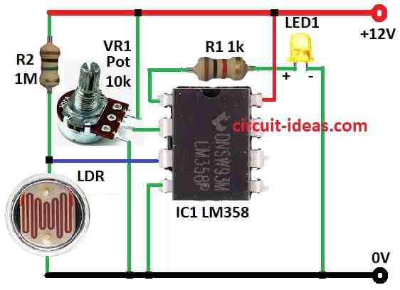
How to Build:
To build a Simple Electronic Candle using LDR follow the below mentioned steps for connections:
- Collect all parts like shown in circuit diagram.
- Connect pin 1 of LM358 IC1 to ground through R1 resistor and LED1.
- Connect pin 2 of IC1 to middle leg of pot VR1.
- Connect pin 3 of IC1 between R2 resistor and LDR.
- Connect pin 4 of IC1 to ground.
- Connect pin 8 of IC1 to +12V power.
- Connect R1 and LDR from (+) supply to (−) ground.
- VR1 potentiometers top leg connects to +12V, middle leg to IC1 pin 2 and last leg to ground.
Extra Notes:
- We can control how bright and dark it needs to be for LED to turn ON by adjusting potentiometer VR1.
- To make LED flicker like real candle can add flicker effect circuit.
Conclusion:
This Simple Electronic Candle Circuit using LDR and IC LM358 as comparator to turn LED ON/OFF by light level.
Change potentiometer to set how dark it needs to be for LED to glow.
It is a simple way to make LED act like a real candle in the dark.