Simple but strong Emergency Lamp Circuit using IC LM358 is an easy to make project.
Circuit is good for backup light when power goes OFF.
Circuit gives automatic light during power cut.
IC LM358 op-amp sense power fail and control the lamp.
It needs 12V battery to run the circuit.
Circuit Working:
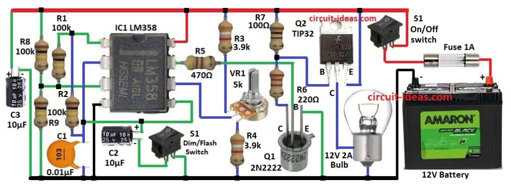
Parts List:
| Component | Value/Type | Quantity |
|---|---|---|
| Resistors (All resistors are 1/4 watt unless specified) | ||
| 100k | 4 | |
| 3.9k | 2 | |
| 470Ω | 1 | |
| 100Ω | 1 | |
| 220Ω 1/2 watt | 1 | |
| Potentiometer 5k | 1 | |
| Capacitors | ||
| Ceramic 0.01µF | 1 | |
| Electrolytic 10µF 25V | 2 | |
| Semiconductors | ||
| IC LM358 | 1 | |
| Transistor 2N2222 | 1 | |
| Transistor TIP32 | 1 | |
| Switch ON/OFF | 2 | |
| Fuse 2A | 1 | |
| Battery 12V | 1 |
Circuit uses op-amp chip LM358.
IC1 work like oscillator and comparator and makes pulse signal to flash or steady light which depend on switch S1.
IC1 control two transistors Q1 2N2222 and Q2 TIP32.
R5 control base current for Q1.
R6 limits the base current for Q2 and make it switch proper.
R7 keeps circuit stable and control current flow.
R8 and R9 make voltage divider for IC bias.
C2 smooth signal for timing.
C3 keep power supply stable.
S1 change between Dim and Flash mode.
VR1 adjust IC sensitivity and set voltage point for lamp ON/OFF.
When main power is ON then battery is ready and lamp goes OFF.
When power fails then circuit sense drop and turns Q2 ON and lits lamp light with 12V battery.
Formulas with Calculations:
Below are the formulas with calculations for Simple Emergency Lamp Circuit using IC LM358:
Oscillation frequency IC1:
f = 1 / (2π × √(R1 × C1 × C2))
where,
- R1 = 100kΩ, C1 = 0.01µF, C2 = 10µF
f = 1.59 Hz
Base current Q1 2N2222:
I_B = (12 – 0.7) / 470 = 24 mA
Collector current Q2 TIP32:
I_C = β × I_B = 100 × 0.024 = 2.4A good for 2A lamp
Power in R6 220Ω:
P = (0.024)² × 220 = 0.127 W safe for 0.5W resistors suitable for switching it.
How to Build:
To build a Simple Emergency Lamp Circuit using IC LM358 following steps are required for connections of the circuit:
- Gather all parts as shown in circuit diagram
- Pin 1 connects to pin 3 through R1.
- Pin 2 connects to GND through C1.
- Pin 3 goes between R8 and R9.
- Pin 4 connects to GND.
- Pin 5 connects to pin 2.
- R2 goes from pin 1 and Pin 2.
- C2 anode connects between pin 5 and pin 2 and cathode goes to S1 and other side of S1 and GND.
- Pin 6 goes middle of VR1 and VR1 top pin goes to R3 and VR1 bottom pin goes to R4.
- Pin 7 connects from Q1 base through R5.
- Pin 8 connects to +12V battery.
- Q1 collector connects to R6, R7 and Q1 emitter connects to GND.
- Q2 base goes R4 and R7.
- Q2 collector goes to on end of bulb and other end of bulb side goes to GND.
- Q2 emitter connects to +12V.
- S2 one end connects to +12V and other end connects to fuse and other end of fuse connects to positive of battery and battery negative goes to GND.
- C2 positive connects to +12V and negative connects to GND.
Conclusion:
This Emergency Lamp Circuit using IC LM358 is simple and works well.
It works auto when power is OFF and can flash or be steady.
LM358 sense power fail and then transistors switch the lamp.
This circuit is good and easy project for DIY.