Ever wondered how fog horns make that deep, spooky sound?
This Fog Horn Circuit is a small sound-making device.
It uses electronics to make the low, rising and falling fog horn noise.
People use these circuits for fun projects or to learn about electronics.
Circuit Working:
Parts List:
| Component | Value/Type | Quantity |
|---|---|---|
| Resistors( All resistors are 1/4 watt unless specified) | ||
| 100Ω | 1 | |
| 1k | 2 | |
| 68k | 2 | |
| Capacitors | ||
| Ceramic 100nF | 2 | |
| Electrolytic 100µF 25V | 1 | |
| Semiconductors | ||
| Transistors BC547 | 2 | |
| Transistor BC557 | 1 | |
| Speaker 8Ω | 1 | |
| Push button | 1 | |
| Battery 9V | 1 |
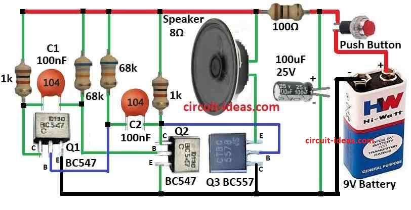
In this article the circuit runs on a 9V battery.
It uses two BC547 transistors and one BC557 transistor in a three-stage amplifier setup to boost the signal from the oscillator.
The oscillator is made of resistors and capacitors.
When we press the push button a 100uF capacitor charges through a 1k resistor.
As it charges the pitch of the sound rises.
When we release the button the capacitor discharges through the speaker and the pitch falls until the sound stops.
An 8Ω speaker plays the sound made by the oscillator.
The push button starts and stops this process creating the fog horns rising and falling sound.
Formulas:
To design a fog horn circuit we need an oscillator to drive a loudspeaker.
Here is a simple explanation with main formulas and parts:
1. Oscillator Design
Use an astable multivibrator to generate the sound signal.
Oscillation Frequency Formula:
f = 1.44 / (R1 + 2 * (R2 + R3)) * C
where,
- R1, R2 and R3 are resistors in the oscillator.
C is the capacitor.
Change resistor and capacitor values to get the fog horns deep tone.
2. Transistor Base Resistor Calculation
To control the transistor BC547 or BC557 calculate the base resistor RB:
RB = (Vin – VBE) / IB
where,
- Vin is the input voltage which is usually 9V
- VBEis the base-emitter voltage drop which is about 0.7V for silicon transistors)
- IB is the desired base current
3. Speaker Current Limiting Resistor:
Protect the 8Ω speaker and ensure proper sound output:
Rspeaker = (Vsupply – Vspeaker) / Ispeaker
- Vsupply is the power supply for 9V
- Vspeaker is the speaker impedance for 8Ω
- Ispeaker is the desired current based on loudness and power rating
4. Circuit Summary
Use BC547 transistors for the oscillator.
Use a BC557 transistor for amplification.
Drive an 8Ω speaker for the sound.
A push button triggers charging/discharging of a capacitor causing the pitch to rise and fall like a real fog horn.
Note: Adjust resistor and capacitor values and test the circuit to fine-tune the sound.
How to Build:
To build a Fog Horn Circuit follow the below mentioned steps for components connections:
Transistor Amplifier Stages:
- The base of the first BC547 transistor connects to a 68k resistor which is connected to the oscillators positive output.
- Its collector connects through a 1k resistor to the base of a second BC547.
- The second BC547s collector goes through another 68k resistor to the base of a BC557 transistor.
- The collector of the BC557 connects to the positive terminal of the speaker.
- The emitters of both BC547 transistors are connected to the batteries negative GND.
- The BC557s emitter connects to one end of the speaker with the other end of the speaker connects to the positive battery terminal.
- A 100nF capacitor C2 connects to the base of the first BC547 Q1 through a 68k resistor.
- One end of another 100nF capacitor C1 connects through a 1k resistor to the base of the BC557 Q3.
- The other end of C1 connects through a 1k resistor to the collector of Q1 and through a 68k resistor to ground.
Conclusion:
This Fog Horn Circuit is a fun and simple electronics project.
It uses capacitors and transistors to create a sound that rises and falls in pitch just like a real fog horn.
We can tweak component values to change the sound and learn about basic electronics in the process.
Always follow safety precautions while building the circuit.
Leave a Reply