Do anyone want to test their grip strength? Like small hand wrestling with ourselves?
This Hand Grip Strength Tester Circuit is a hand grip tester.
It uses simple electronic parts to check how hard we can squeeze.
More squeeze then more lights turn ON which shows our grip power.
Circuit Working:
Parts List:
| Component | Value/Type | Quantity |
|---|---|---|
| Resistors (All resistors are 1/4 watt unless specified) | ||
| 4.7k | 1 | |
| 3.3k | 1 | |
| 2.2k | 2 | |
| 470Ω | 4 | |
| Potentiometer 200k | 1 | |
| Semiconductors | ||
| Transistors BC547 | 5 | |
| LEDs 5mm 20mA | 4 | |
| Diode 1N4148 | 1 | |
| Probes | 2 |
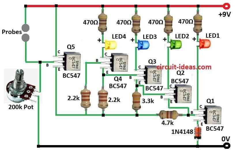
In this circuit it shows how much pressure we give using LEDs and transistors.
How it works:
9V battery gives power to LEDs.
Transistors get signal from resistors in a chain (voltage divider).
One resistor is a 200k potentiometer and it can change.
When we press the probes the resistance goes down.
Then current goes through 470Ω resistors to transistor bases.
If enough current comes then transistor turns ON and LED lights up.
1N4148 diode protects if voltage is backwards.
2.2k and 3.3k resistors help set base voltage when it is not pressed.
4.7k resistor limits LED current.
Potentiometer controls how sensitive circuit is and turn it to make circuit more or less sensitive.
More pressure means more LEDs ON.
We can use this to check our grip strength.
Formulas:
Hand grip strength tester circuit shows grip power using LEDs.
Here are basic formulas to choose right parts:
1. Collector Current (IC):
Use transistor gain (β) and base current (IB):
IC = β × IB
where,
- β for BC547 is about 200
2. Base Resistor RB:
To find RB we can use the formulas:
RB = (Vin − VBE) / IB
where,
- VBE is about 0.7V for silicon transistor.
- Vin is input voltage.
3. LED Resistor RLED:
To keep LED safe which is usually 20mA:
RLED = (Vsupply − VLED) / ILED
where,
- Vsupply is battery voltage.
- VLED is LED drop with around 2V for red LED.
- ILED is LED current like 20mA.
Note:
This circuit uses LEDs, transistors, resistors and potentiometer.
It shows grip power by lighting more LEDs.
These formulas help design the circuit.
Always test parts to get best results.
How to build:
To build a Hand Grip Strength Tester Circuit we need to follow the below mentioned steps:
- Connect (+) side of 9V battery to main point on board.
LEDs:
- Long leg positive of each LED goes to + battery line.
- Short leg negative goes to collector of BC547 transistors Q1 to Q4.
BC547 Transistors:
- Each one has 3 legs: Collector, Base, Emitter.
- Collector connects to LEDs negative leg.
- All Emitters join together and go to ground (–).
- Each Base connects to resistor from voltage divider.
Voltage Divider:
- Made from 200k potentiometer or 4 resistors based on LED count.
- One end of potentiometer to goes to (+) battery.
- Middle wiper pin goes to chain of resistors to ground.
- Base resistors for each transistor connect at different points along with this chain.
Probes:
- Connect between base of Q5 transistor and (+) of battery.
- When we press the resistance drops and current flows to base of transistor and it turns ON.
Diode 1N4148:
- Put across power supply in reverse strip side to negative.
- This protects from battery put in wrong way.
Other Resistors:
- 2.2k / 3.3k resistors go between base of transistors and voltage divider which gives base voltage when it is not press.
- 4.7k resistors go in series with each LED and protect from too much current.
Important:
- This is just general idea but actual connections may change.
- Always follow schematic diagram carefully.
- Double check all wiring before turning ON the circuit.
Conclusion:
This Hand Grip Strength Tester Circuit is simple and good for hobby use.
It is not for medical use.
It is good for accurate testing and for better use in digital grip meter like dynamometer.