This Simple LED Alert for Telephone Off-Hook Detection Circuit shows when phone is in use by turning ON the LED.
It checks voltage change when handset is lifted means off-hook.
Circuit is good for old phones with no light alert.
It is very useful for shared phones and stops call interruptions.
Circuit runs on simple 3V battery which is easy and practical.
Circuit Working:
Parts List:
| Component | Quantity |
|---|---|
| Resistors (All resistors are 1/4 watt unless specified) | |
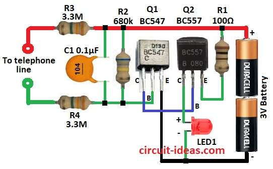
| R1 100Ω | 1 |
| R2 680k | 1 |
| R3, R4 3.3M | 2 |
| Capacitors | |
| C1 Ceramic 0.1µF | 1 |
| Semiconductors | |
| Q1 NPN BC547 | 1 |
| Q2 PNP BC557 | 1 |
| LED1 5mm 20mA | 1 |
| Battery 3V | 1 |
The circuit connects to phone line using resistors R3 and R4.
These resistors limit current and protect from high voltage.
Capacitor C1 blocks DC but allows AC to pass.
Resistor R2 helps transistor Q1 BC547 work right.
When phone goes off-hook then line voltage drops and this turns ON the Q1 transistor.
Q1 then turns ON Q2 BC557 which lights LED1 through R1.
Whole circuit runs on 3V battery.
LED stays ON while phone is off-hook by showing line is busy.
Formulas with Calculations:
Voltage Divider (R3, R4):
Q1 base voltage:
V_base = (V_line × R4) / (R3 + R4)
Both R3 and R4 = 3.3MΩ
On-Hook (V_line = 48V):
V_base = 48V × (1/2) = 24V
Off-Hook (V_line = 9V):
V_base = 9V × (1/2) = 4.5V
Q1 Base Current (I_B):
Transistor Q1 turns on if base-emitter voltage (V_BE) ≥ 0.7V
Use:
I_B = (V_base – V_BE) / R2
R2 = 680kΩ
I_B = (4.5V – 0.7V) / 680kΩ = 5.58µA
Q1 Collector Current (I_C):
Use transistor gain β = 100:
I_C = β × I_B
I_C = 100 × 5.58µA = 0.558mA
This turns on Q2.
LED Current (I_LED):
Q2 ON and LED1 gets current via R1 (100Ω)
LED drop = 2V, battery = 3V
I_LED = (3V – 2V) / 100Ω = 10mA
10mA is safe for LED.
All values show circuit works good with 3V battery and gives LED alert when phone is off-hook.
How to Build:
To build a Simple LED Alert for Telephone Off-Hook Detection Circuit following steps are needed to be followed:
- Q1 base connects to one end of R2
- Other end of R2 connects to +3V supply
- Q1 collector connects to base of Q2
- Q1 emitter connects to GND
- Q2 emitter connects to one end of R1
- Other end of R1 connects to +3V supply
- Q2 collector connects to anode of LED1
- LED1 cathode connects to GND
- C1 one end connects to +3V and other end connects to GND
- R3 and R4 connect between C1 and phone line
- Battery+3V connects to circuit positive and negative connects to GND
Conclusion:
This Simple LED Alert for Telephone Off-Hook Detection Circuit shows when phone is in use.
It uses low power LED, saves battery and works long time.
Circuit is easy to build and is good for shared phones.
It stops call cuts and helps manage calls better.
Leave a Reply