Mosquito repellers are popular to keep bugs away, as they use ultrasonic sound or chemical spray; but if it is always ON then they use much electricity.
To solve this problem, we designed a timer-based mosquito repeller power saver circuit, it switches the repeller ON and OFF at fixed intervals to reduce power consumption and increase operational efficiency.
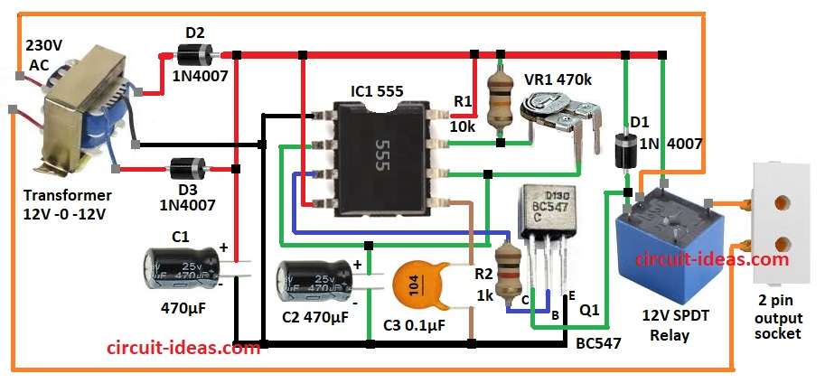
Main part of this circuit is astable multivibrator using timer IC 555.
Circuit Working:
Parts List:
| Components | Values | Quantity |
|---|---|---|
| Resistors (All resistors are 1/4 watt unless specified) | 10k | 1 |
| 1k | 1 | |
| Preset 470k | 1 | |
| Capacitors | Ceramic 0.1µF | 1 |
| Electrolytic 470µF 25V | 2 | |
| Semiconductors | Timer IC 555 | 1 |
| Transistor BC547 | 1 | |
| Diode 1N4007 | 3 | |
| Relay 12V SPDT | 1 | |
| Step-Down Transformer 12V from 230V AC | 1 | |
| Output Socket 2 pin | 1 |
This circuit uses 555 timer to set as astable multivibrator, as this timer gives ON and OFF signals again and again.
First, a transformer converts 230V AC to 12V AC and then diodes D1, D2 and D3 convert the AC into DC.
Then this DC powers the entire circuit using a 555 timer and a relay driver and VR1, R1 and capacitor C1 set the timing and control how long the ON and OFF periods last.
Also, timer makes pulsed signals with HIGH and LOW and when output is HIGH relay turns ON and mosquito repeller works and when output is LOW then relay turns OFF and repeller stops.
As a result, this happens again and again by itself and then transistor Q1 works like a switch for the relay.
When output is HIGH then Q1 lets current flow and relay and repeller turns ON and therefore, when output is LOW then Q1 stops current and relay and repeller turns OFF.
Formulas with Calculations:
Formulas and values for Timer Based Mosquito Repeller Circuit:
Astable Multivibrator Formulas:
ON Time (T_HIGH):
T_HIGH = 0.693 × (VR1 + R1) × C1
OFF Time (T_LOW):
T_LOW = 0.693 × R1 × C1
Total Time (T):
T = T_HIGH + T_LOW
Frequency (f):
f = 1 / T
where,
- VR1 is 470kΩ
- R1 is 10kΩ
- C1 is 470µF
Calculate ON Time:
T_HIGH = 0.693 × (470k + 10k) × 470µF
= 0.693 × 480,000 × 0.00047
= 156.2 sec
Calculate OFF Time:
T_LOW = 0.693 × 10,000 × 0.00047
= 3.25 sec
Total Time:
T = 156.2 + 3.25 = 159.45 sec
Frequency:
f = 1 / 159.45 = 0.00627 Hz
This means circuit turns mosquito repeller ON for 156 sec and OFF for 3 sec and then repeats again and again.
How to Build:
To build a Timer Based Mosquito Repeller Power Saver Circuit follow below steps for connection:
- First, gather all the parts as shown in circuit diagram Connect pin 1 of IC1 to GND.
- Join pin 2 and pin 6 of IC1 together, then connect C2 positive to pin 2 and negative to GND.
- Then connect pin 3 of IC1 to base of transistor Q1 using resistor R2.
- Now connect pin 4 and pin 8 of IC1 to positive supply.
- Next, connect capacitor C3 between pin 5 and GND.
- Also, connect one side of VR1 to pin 6 and other side to pin 7 and also connect one side of R1 to pin 7 and other side to positive supply.
- Further, connect collector of Q1 between diode D1 and 12V relay and then connect emitter of Q1 to GND.
- Then connect diodes D2 and D3 to transformer primary pins.
- Finally, one output socket pin goes to transformer secondary pin and other output socket pin goes to SPDT relay.
Conclusion:
To conclude, this Timer Based Mosquito Repeller Power Saver Circuit with 555 IC chip is smart project, as it turns repeller ON and OFF on time and saves power.
Also, repeller works well with no power waste and we can also change timing as needed.
Moreover, the circuit is simple and is useful way to save energy.
Leave a Reply