LM317 IC Solar Charger Circuit with Auto Cut off works like smart nanny for a battery, as it takes sunlight and charge battery but stop at right time.
Also, inside it have one smart chip called LM317 which control charging and gives battery only needed power which is not too much.
The best part is that it also includes a safety feature that automatically cuts off charging when the battery becomes full, which prevents overcharging and battery damage.
Hence, one should just sit back, relax and enjoy solar power for its own use.
Circuit Working:
Parts List:
| Components | Values | Quantity |
|---|---|---|
| Resistors (All resistors are 1/4 watt unless specified) | 180Ω | 1 |
| 1k | 1 | |
| 10Ω 1W | 1 | |
| Preset 1k | 1 | |
| Semiconductors | IC LM317 | 1 |
| Transistor BC547 | 1 | |
| Zener diode (as shown in diagram) | 1 | |
| Diodes 1N4007 | 2 | |
| Solar Panel (as shown in diagram) | 1 | |
| Battery 6V to 24V | 1 |
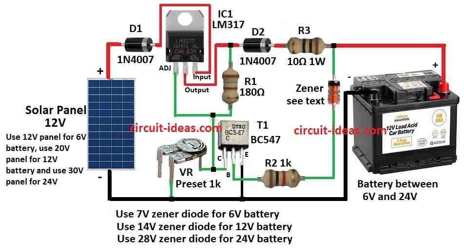
This circuit makes solar charger to charge Lead Acid or Ni-Cd battery using sun power, also it uses solar energy smartly to charge 6V, 12V or 24V battery which are good for many things.
Charger have voltage and current control which also protect from too much voltage, as it uses solar panel for 6V, 12V or 24V and one adjustable chip called LM317.
Here, the charging current go through diode D1 into LM317 chip and we can change output voltage and current by adjusting adjust pin of LM317.
One variable resistor VR connects between the adjust pin and ground to set the output around 9V for charging the battery, resistor R3 limits excess current and diode D2 prevents the battery from discharging backward.
Furthermore, one transistor T1 and Zener diode work together to stop charging when battery is full; normally T1 stay OFF so battery keep getting charge.
But when battery voltage go more than Zener diode value then Zener start working and send current to T1 and then T1 turns ON and connect LM317 output to ground and so the charging stops.
Formula:
Below is simple diagram and formula for LM317 solar charger with auto cut off.
LM317 Voltage Setup:
The LM317 works as a voltage controller in this design and this formula can calculate the output voltage (Vout):
Vout = Vref × (1 + R2 / R1) + Iadj × R2
where:
- Vref fixed voltage of LM317which is about 1.25V
- R1 and R2 are resistors in divider setup
- Iadj is small current from adjust pin from around 50 microamps
Note:
This simple diagram and formula help anyone build their own LM317 solar charger with auto cut off based on the required battery or setup and they only need to change the values according to their use.
How to Build:
To build an LM317 IC Solar Charger Circuit with Auto Cut off follow these below steps:
- First, place LM317 IC on breadboard and connect pin 3 input to + positive of solar panel.
- Then connect pin 2 output to + positive of battery and connect pin 1 adjust to resistor setup.
- After that, connect 180 ohm resistor from pin 1 adjust to pin 2 output.
- Now connect 1k resistor from base of transistor T1 to + positive through Zener diode.
- Next, connect collector of transistor to pin 2 output of LM317, connect emitter of transistor to ground and connect base of transistor to Zener diode and also connect the other side of Zener to ground.
- Also, put diode D1 1N4007 between solar panel + positive and LM317 input to stop reverse current.
- And then put diode D2 1N4007 between battery + positive and LM317 output to stop reverse current and then connect – negative of solar panel and battery both to ground.
Test the Circuit:
- Put solar panel in sunlight and see if battery is charging and watch transistor and Zener and when battery is full they should stop charging.
Finish the Circuit:
- If all is working fine build it on PCB or make it more permanent.
Note:
- Hence, be careful when working with circuits and also use safety glasses and check of any short circuits please.
Conclusion:
Overall, this LM317 IC Solar Charger Circuit with Auto Cut off is smart and easy way to charge Lead Acid or Ni-Cd batteries using sunlight.
Also, it use LM317 chip to control voltage and current and also stop charging when battery is full so there wont be any overcharge.
Finally, with right parts and design, this circuit is cheap and good for environment and one can use it in many solar charging projects.