LED needs stable current and when current becomes high then LED may burn, therefore, a regulator circuit is useful.
This article is for Simple LM337 Based Precision LED Driver Circuit which is an negative adjustable voltage regulator but however, it can also control current.
In this circuit the LED current stays stable and even if input voltage changes the LED current remains nearly same.
Therefore, the LED brightness becomes stable and also LED life becomes longer.
Because of this, the circuit is good for precision LED applications.
Circuit Working:
Parts List:
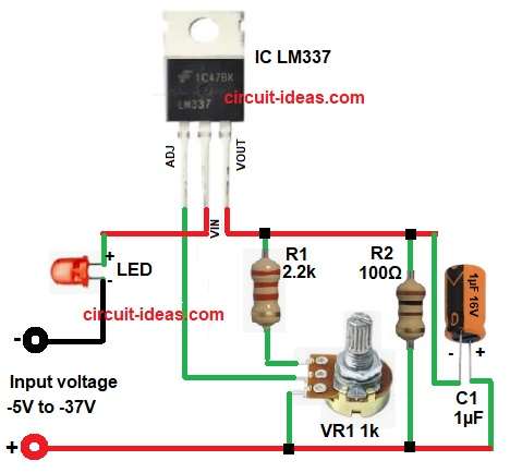
| Components | Values | Description |
|---|---|---|
| Resistors | 100Ω, 2.2k 1/4 watts | 1 each |
| Potentiometer 1k | 1 | |
| Capacitors | Electrolytic 1µF 16V | 1 |
| Semiconductors | IC LM337 | 1 |
| LED1 Standard LED 5mm | 1 | |
| DC Power Supply or Battery -5V to -37V | 1 |
First, the negative supply voltage goes to the input pin of LM337 and its supply can be from about -5V to -37V.
Next, the LM337 tries to maintain a constant reference voltage between the output and adjust pin.
Because of this reference voltage, a constant current flows through resistor R2.
After that, the same current flows through the LED and therefore, an LED current becomes regulated.
Meanwhile, VR1 adjusts the current level, so the user can control LED brightness.
Also capacitor C1 helps to reduce noise and therefore, the circuit becomes more stable.
Finally, the LED lights with controlled and stable current.
Formula with Calculation:
The LM337 keeps a reference voltage of about 1.25V.
LED current mainly depends on resistor value.
Formula for current:
I = Vref / R
where,
- I is the LED current
- Vref is the 1.25V for LM337 reference voltage
- R is the resistor value in ohms
Example for calculation:
If R2 = 100 ohm
I = 1.25 / 100
I = 0.0125 A
I = 12.5 mA
So LED current will be about 12.5 mA.
Note: If resistor value becomes smaller then current increases and if resistor value becomes larger then current decreases.
How to Build:
To build a Simple LM337 Based Precision LED Driver Circuit follow the below connection steps:
- Start, the circuit first by assembling all the circuit components as in diagram above.
- Then start with IC LM337 pin Adjust connect to middle pin of VR1 pot.
- Then pin input of IC connect to negative supply of -5V to -37V through LED.
- Then output pin of IC connect to resistors R1, R2 and capacitor C1 network.
- Connect capacitor C1 between output pin of IC and positive supply.
- Connect resistor R2 between output pin of IC and positive supply.
- Connect resistor R1 between output pin of IC and one end of VR1 pot and other end of pot goes to positive supply.
Conclusion:
Simple LM337 Based Precision LED Driver Circuit is simple and useful project which uses very few components, also the circuit gives stable LED current.
Therefore, LED brightness stays constant.
In addition the LED becomes protected from over current, because of these advantages this circuit is good for indicator LEDs, test equipment LEDs and precision lighting applications.
Leave a Reply