Simple Mobile Phone Signal Jammer Circuit is device that stop signal between phone and tower, it does this by using same radio frequency like phone and to make communication not to work.
Also, this small circuit can block call and message on 3G, 4G and also old network.
Here, three main part inside jammer are:
First is the amplifier which make signal more strong.
Second one is special circuit which creates right type radio waves.
Third the device then modifies these waves so they can interfere with the phone signal and when all the parts work together, they jam the phone signal.
WARNING: In many countries jammers are illegal to use, sell or make and using jammer can cause fine or jail in some places.
Emergency services such as ambulances and police require clear communication signal, and this jammer circuit can interfere with them.
Therefore, only government agencies such as the military or police are sometimes permitted to use such devices.
Circuit working:
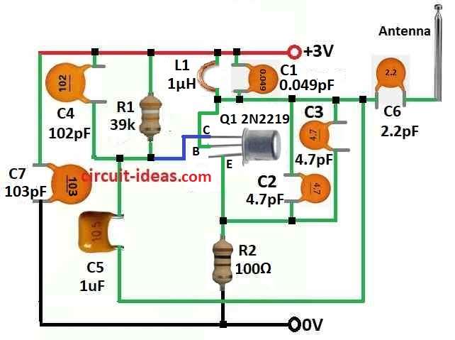
Parts List:
| Components | Quantity |
|---|---|
| Resistors (All resistors are 1/4 watt) | |
| 39k | 1 |
| 100Ω | 1 |
| Capacitors | |
| Ceramic 0.049pF | 1 |
| Ceramic 102pF | 1 |
| Ceramic 1uF | 1 |
| Ceramic 2.2pF | 1 |
| Ceramic 103pF | 1 |
| Ceramic 4.7pF | 2 |
| Semiconductors | |
| Transistor 2N2219 | 1 |
| Inductor 1uH | 1 |
| Antenna | 1 |
RF amplifier circuit have transistor Q1, capacitors C4, C5 and resistor R1.
Also, this circuit make signal from tuned circuit which is more strong and then signal goes to antenna by capacitor C6 and this C6 stop DC but let AC go.
When transistor Q1 turns ON, tuned circuit at collector also start working and this tuned circuit have capacitor C1 and inductor L1 which works like oscillator with very small resistance to make very high frequency.
Furthermore, this happen because capacitor charges and discharges again and again and it also make oscillation but after some time small resistance come and stop oscillation.
Before C6, the tuned circuit boosts and mixes the frequency with noise from capacitors C2 and C3.
The RF amplifier then sends power to the collector through capacitor C5, producing a strong combined signal for transmission.
Here, mobile phones use different frequency bands in world and to make jammer circuit we have used one formula to find correct values.
Value of inductor L1 and capacitor C1 can change depending which frequency we want to block.
Example, if phone in area use 450 MHz then jammer also make 450 MHz with noise, hence, this confuses the phone and it cannot catch right signal.
Note : This circuit only work around 100 meter distance.
Important: Also using this circuit is illegal in most countries, so remember this information is only for learning not for any misuse.
Formula:
Resonant frequency (F) of simple LC circuit we find by this formula:
F = 1 / (2 × π × √(L1 × C1))
where:
- F is frequency in hertz Hz which shows max oscillation of circuit.
- π (pi) is math value which is about 3.14159.
- L1 is inductor value in Henrys H where inductor stops fast to change in current and store energy in magnetic field.
- C1 is capacitor value in farads F where capacitor store electric energy in electrostatic field.
About the Formula:
This formula connect inductance L1 and capacitance C1 to find frequency.
In LC circuit when inductor and capacitor gives same opposite reactance it make resonance, hence, this means inductors reactance XL and capacitors reactance XC cancel each other.
Square Root Part (√(L1 × C1)):
This show how much inductor and capacitor affect circuit together and at resonance this effect becomes zero.
2π Factor:
We use 2π to convert reactance into frequency because, in AC circuits, frequency and reactance are directly related.
In simple words:
Therefore, this formula tell what frequency LC circuit will resonate and it happen when inductor and capacitor balance each others effect.
Conclusion:
To conclude, many countries prohibit this Simple Mobile Phone Signal Jammer Circuit because it can block important communication and emergency calls.
Lastly, they also make trouble for other people using phone in legal way nearby and also making jammer at home is also not legal, even for fun or learning.
So it is very important to build or use this kind of device as it against the law.