Nickel Cadmium (Ni-Cd) batteries are very common for rechargeable use.
They give good power and work long time with many charges.
To charge them right we need a special charger made for Ni-Cd.
Mostly it is for 12V Ni-Cd battery pack.
This article for Ni-Cd Battery Charger Circuit using Transistors shows simple and strong charger circuit.
It explains how it works, the calculations, and how to build it.
Circuit Working:
Parts List:
| Component | Quantity |
|---|---|
| Resistors | |
| 0.15Ω 3W | 1 |
| 2.7k 1/4 Watt | 1 |
| 100Ω 1/4 Watt | 1 |
| 22Ω 1W | 1 |
| 220Ω 0.5W | 2 |
| Semiconductors | |
| PNP Transistor BC557 | 1 |
| NPN Transistor 2N2222 | 2 |
| NPN Transistor TIP31 | 1 |
| Transformer 230V primary 12V secondary 4A | 1 |
| Bridge Rectifier 1N5400 | 4 |
| Fuse 500mA | 1 |
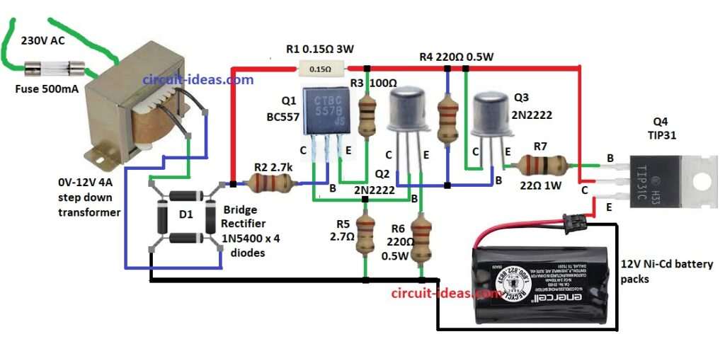
This circuit shows how Ni-Cd battery charger works.
It gives steady current while charging.
First the transformer makes 230V AC into low AC voltage.
Then bridge rectifier D1 changes AC to DC.
Transistors control charging current to keep battery safe.
Q1, Q2 and Q3 keep current steady.
Q4 TIP31 removes extra power as heat.
Resistors R1 to R7 control current and give right bias.
Fuse F1 500mA stops too much current.
Charger works in constant current mode for safe charging.
Formulas with Calculations:
Transformer Selection:
Battery needs 12V DC.
With drops the transformer should give:
Vsecondary = 12V + 3V = 15V
Charging Current:
Ni-Cd charge current = Battery Capacity ÷ 10
If battery is 1.5Ah
Icharge = 1.5Ah ÷ 10 = 150mA
Resistor R1 for current sense:
R1 = 0.15Ω, 3W
Voltage across R1:
VR1 = 0.15A × 0.15Ω = 0.0225V
Power Loss in Q4 (TIP31):
PQ4 = (Vinput − Vbattery) × Icharge
It tells how much heat Q4 makes.
How to Build:
To build a Ni-Cd Battery Charger Circuit using Transistors follow the below mentioned steps for connections and assembling:
- Take all parts as in circuit diagram.
- Connect Q1 collector to Q2 base.
- Q1 base goes to one side of R2 and other side of R2 to D1 of bridge rectifier.
- Q1 emitter goes to positive supply through R3.
- Q2 collector goes to Q3 base.
- Q2 base connects to Q1 collector.
- Q2 emitter goes to GND through R6.
- Q3 collector connects to positive supply.
- Q3 base connects to Q2 collector.
- Q3 emitter connects to Q4 base through R7.
- Q4 collector connects to D1 through R1.
- Q4 emitter goes to positive of 12V Ni-Cd battery and battery goes to GND.
- Connect D1 pin to one wire of transformer.
- Other transformer wire goes to third pin of D1.
- Fourth pin of D1 connects to GND.
- Put fuse on 230V AC for protection.
Conclusion:
This Ni-Cd Battery Charger Circuit using Transistors is safe and works well.
Transistors keep current steady and this helps battery live longer.
It is important to control heat and use correct parts.
We can change resistor values to charge other battery sizes.
Leave a Reply