Simple Power Strip Surge Protector Circuit is like hero for our plugs, they help protect our devices from big shock of electricity called power surge or spike.
Also, this surge can come when storm happen or when other machine turn ON or OFF.
Inside power strip a special part called MOV take this extra electricity and send it away, so our devices do not get damage; hence we can put all our device in power strip and do not worry about surprise electric shocks from the wall.
Circuit Working:
Parts List:
| Components | Values | Quantity |
|---|---|---|
| Capacitors | PPC 0.1µF 400V | 1 |
| PPC 4712KV | 2 | |
| MOV 431KD14 | 1 | |
| Semiconductors | Coil (pair of 20 Turns 22 SWG) | 1 |
| Fuse | 1 |
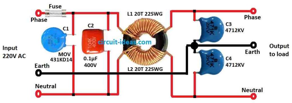
This circuit is for power strip surge protector, it protect power supply units from bad electricity.
Also we can find this kind of spike protector in multi socket switchboards which are mostly for computer parts connection.
Furthermore, this circuit help to save electric and electronic things from high voltage spike and transients from power line.
If big spike come in mains line, the MOV (metal oxide varistor) in circuit will make short circuit and then fuse will break to stop damage.
Power supply guard circuit have MOV 431KD14, one 0.1uF X2 type AC capacitor, one toroidal transformer and two disc capacitors of 2kV.
Here, the MOV is a small device made from zinc oxide and other metal oxides such as bismuth, cobalt and manganese, placed between two metal plates (electrodes).
Each small grain touch other grain and make diode junction and this let current connect in one side only and when voltage is small with only little current connection very small leakage take place.
Therefore, applying a high voltage generates heat and electron tunneling, which break down the diode junction and allow a large current to flow.
The varistor then absorbs part of the surge to provide protection and the amount of protection depends on the type of varistor and the device it protects.
Formula:
From above circuit diagram we can use formula to find coil inductor value and this inductor can help to block high frequency spike or remove noise from power line.
We can calculate the inductive reactance XL of an inductor by using this formula:
XL = 2 × π × f × L
where:
- XL is inductive reactance in Ohm Ω
- π (pi) is math constant which is around 3.14
- L is inductance of coil in Henry H
- f is frequency of power in Hertz Hz
Note:
This formula help to know single part but full surge protector circuit depend on many other things.
A power strip surge protector handles specific voltage and surge current levels, but we must follow proper safety precautions when building a surge protector circuit.
Its always better to ask trained electrical person and follow safety rules.
How to Build:
To build a Simple Power Strip Surge Protector Circuit follow the below mentioned steps:
- First, connect one side of C1 MOV (metal oxide varistor) to live wire of input power.
- Then connect the other side of the MOV to one side of the C2 AC-rated capacitor.
- Now connect other side of C2 capacitor to live terminal of output power line.
- Next, take neutral wire from input power and connect it straight to neutral terminal of output power.
- Now connect toroidal transformer between live and neutral terminals of output power.
- At last connect two 2kV disc capacitors across the output terminals and these will give extra protection from spike.
Note:
- Be very careful while working with main electricity and always turn OFF power before touching wires.
- Use only components that are good for voltage and current in the circuit and if anyone is not sure about electronics then better to ask expert.
Conclusion:
To conclude, Simple Power strip surge protector circuit is very important part in power strip; as it helps to save electronic things from big voltage spike and surge.
Also, this circuit uses parts like metal oxide varistor (MOV) to send extra voltage to ground and this way our device do not get damage.

Leave a Reply