Think like anyone have one small device to check its home electricity going up and down; then this Mains AC Transients Indicator Circuit is same like that but only for sudden high voltage.
These high voltage come from lightning and big machine turning ON or power change, also this circuit have one sensor who is always checking the voltage.
Also, if voltage goes too high and circuit make buzzer sound or lights ON, so one knows spike has happen.
Circuit Working:
Parts List:
| Components | Quantity |
|---|---|
| Resistors | |
| 100k 1/4 watt | 2 |
| 100Ω 1/4 watt | 2 |
| Preset 5k | 1 |
| Capacitors | |
| Ceramic 0.1µF | 1 |
| Electrolytic 1000µF 25V | 1 |
| Electrolytic 10µF 25V | 1 |
| Semiconductors | |
| IC 555 | 1 |
| Diodes 1N4007 | 4 |
| Zener diode 5.1V | 1 |
| Buzzer | 1 |
| Transformer 0-12V 500mA | 1 |
Instant voltage going up and down is very common in power lines, especially in places where big machines operate.
Big coil machines and high power transformers can make sudden spikes and jumps in power lines and these voltage changes can hurt SMPS power supply and microcontroller devices.
Furthermore, this is one small simple circuit that always watch the power line and when the voltage change happen it makes beep sound.
Also, this circuit help one to know when voltage goes too low or too high in power line used for SMPS and microcontroller devices.
Even a 10V voltage spike can cause errors or data loss in these devices and these voltage changes affect SMPS power supplies very easily.
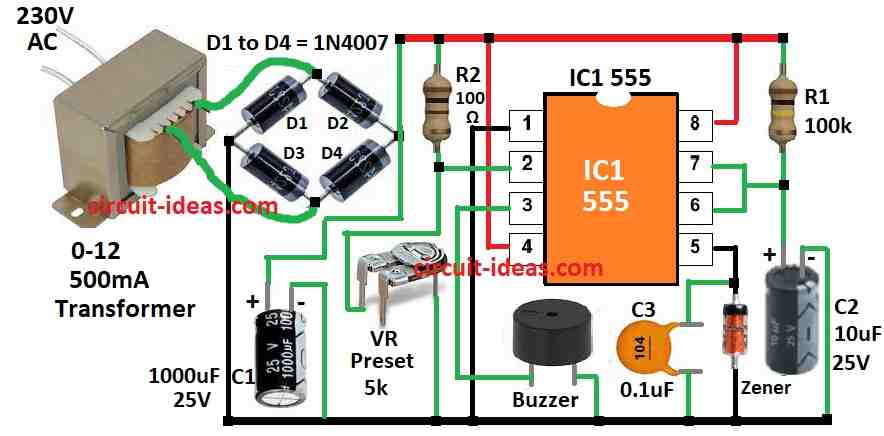
Moreover, this circuit uses a 555 timer IC in monostable mode along with R1 and C2.
Therefore, power for circuit comes from 0 to 12V step down transformer which has bridge rectifier D1 to D4 and one capacitor C1 to make voltage smooth.
If transformers main voltage changes then same change come in output voltage also.
Pin 2 of IC1 is the trigger pin and connects with R2 and VR as a voltage divider, while the VR sets the voltage level on pin 2 slightly above the trigger point, so the IC1 output stays low when the voltage is normal.
But if voltage goes low then voltage on pin 2 also goes down and it trigger the IC and then buzzer makes beep sound to tell that spike has happened.
Lastly, if beep sound happen again and again it is better to remove plug of the devices to keep them safe.
Formula:
One easy circuit called as Mains AC Transients Indicator Circuit helps to find and show spikes like transients in AC mains voltage.
The 555 timer IC works in monostable mode and makes one short pulse when a spike happens, also to find how long the output pulse stays ON, use this formula:
Monostable Mode Formula:
T = 1.1× R × C
where,
- R is the resistor between pin 7 is discharge and pin 6 is threshold of 555 IC.
- C the capacitor connected from pin 7 discharge to ground.
This circuit uses only simple parts which is good for learning and how to find spikes in AC mains power and we can also change R and C values to adjust how long the output will stay ON.
How to Build:
Below mentioned are the steps to build a Mains AC Transients Indicator Circuit:
Power Supply:
- First, connect plus side of bridge rectifier to plus line on breadboard or PCB and then connect minus side to ground.
IC Setup:
- Next, put 555 IC1 on PCB and connect pin 8 to plus line and pin 1 to ground.
Timing Parts:
- Then connect R1 100k between pin 7 and pin 6 of IC1 and connect C2 10uF from pin 6 to ground.
Threshold Voltage Set:
- Now make one resistor divider using R2 10k and VR 5k preset and connect between +12V and ground.
- Connect middle point of R2 and VR to pin 2 of IC1 and this control trigger voltage.
Buzzer Connection:
- Next, connect buzzer plus side to pin 3 of IC1 and minus side of buzzer will go to ground.
Power for IC:
- Put big capacitor C1 1000uF between +12V and ground as this gives smooth power to IC.
Transformer Setup:
- Connect secondary side of step down transformer to rectifier and primary side will connect to the mains power.
Testing the Circuit:
- Turn ON the power and then move VR slowly until buzzer makes sound and now circuit will beep when voltage change happen in mains power.
- Be careful with mains power and if one is not aware of how to work with high voltage then ask help from expert person.
Conclusion:
Overall, this Mains AC Transients Indicator Circuit is very helpful to find voltage spikes in AC power line, as it helps to protect sensitive electronic things from damage and ensures they work smooth.
Also, putting this circuit inside electronic device can make it work better and last longer.
Leave a Reply