
With booster, this small Radio Circuit with Headphones work almost like crystal radio, also it uses 10-foot antenna which catches many nearby strong radio stations.
Longer antenna can catch more stations but also bring unwanted channels, so when trying to hear weak station sometimes other strong station sound come in background.
Hence, for better tuning try connecting long wire antenna straight to coil and not to coil and capacitor join point.
Also, good ground connection is also very important; and if we just want to hear local station then just touching headphone wire to outside concrete is also okay.
Circuit Working:
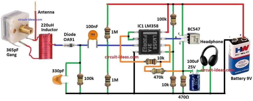
Parts List:
| Components | Values | Quantity |
|---|---|---|
| Resistors | 100k, 1M, 10K (1/4 watt) | 2 each |
| 470k, 470Ω (1/4 watt) | 1 each | |
| Capacitors | Ceramic 100nF | 1 |
| Ceramic 330pF | 1 | |
| Electrolytic100uF 25V | 1 | |
| Gang 365pF | 1 | |
| Semiconductors | Transistor BC547 | 1 |
| IC LM358 | 1 | |
| Diode OA91 | 1 | |
| Inductor 220uH | 1 | |
| Antenna | 1 | |
| Headphone | 1 | |
| Battery 9V | 1 |
To begin with, to make inductor coil take 200 turns of 28SWG copper wire enameled and wind on 4 inch PVC pipe around 7 to 8 inch diameter, this will make inductor about 220uH.
Also, for better connection between diode and antenna make taps every 20 turns and this will last 60 turns which will go to antenna and then to diode.
Here, silicon diode can work if signal is strong but germanium diode gives better result, so use 0.1uF capacitor is to send to audio signal to non-inverting input of op-amp and this op-amp work as buffer with high input.
Also, use 300pF capacitor to pull carrier signal from diode cathode after rectification.
Next op-amp stage connects by 10k resistor and it will boost signal about 50 times and to keep DC voltage at transistor emitter between 3 to 6V we must use resistors with close values; or put one capacitor with the 10k resistor if 100k and 1M resistors do not match well like1% difference.
Thus, another way is to use smaller feedback resistor like 470k to control gain.
Stereo headphones also can use but high impedance headphones sound better, but one 9V battery gives near 10mA power to this radio circuit.
Formula:
Parts Needed for Radio with Headphones Circuit; to build small radio circuit we need few parts with headphones.
Radio work on AM Amplitude Modulation idea.
AM Basics:
AM help to send information like music or voice on radio.
Carrier Wave:
Carrier wave is high frequency wave that carry signal.
Formula is:
Ac × sin(2πfc × t + φ) = v(t)
- v(t) is voltage at time t
- Ac is amplitude of wave
- fc is frequency in Hz
- φ is phase which is usually zero
AM radios work in range from 535 kHz to 1605 kHz.
Information Signal:
This is real sound like voice or music and it is at low frequency signal audio which changes in sound shown as wave.
Amplitude Modulation:
In AM the carrier waves amplitude changes as per audio signal.
Formula:
vAM(t) = Ac × [1 + m × sin(2πfm × t)] × sin(2πfc × t + φ)
- vAM(t) is voltage of AM wave
- m is modulation index (0 to 1) which shows how much carrier changes
- fm is frequency of sound signal from 20 Hz to 20 kHz
Sidebands:
AM creates two extra signals like sidebands:
fc – fm → lower sideband
fc + fm → upper sideband
These sidebands carry the actual voice/music data.
Note:
These maths help to understand how AM radio works and to really make AM transmitter we need more advanced circuit.
How to Build:
To build a Radio Circuit with Headphones follow the connections steps mentioned below:
Putting Inductor Together:
- First, take 4 inch long PVC pipe with 7 to 8 inch wide and wind 200 turns of 28SWG enameled copper wire on it.
- Hence, this will make one inductor value around 220uH.
Putting Antenna Together:
- After that, take 10 foot wire and connect it to middle part of coil and this will help with tuning and better station selection.
Diode Connection:
- Then connect coil to diode and after every 20 turns add one terminal.
- Also, last 60 turns goes to antenna and end at diode.
Audio Frequency Section:
- Next, use 300pF capacitor to take out carrier signal from diode cathode after rectification; and use 0.1uF capacitor to send audio signal into LM1458 op-amp non-inverting input.
- As a result, this op-amp work like buffer high impedance input.
Amplifier Stage:
- Also, to make signal louder to about 50 times use second op-amp from LM1458 and connect output of first op-amp to second op-amp with 10k resistor.
Resistor Adjustment:
- Then use 100k and 1 Meg resistors with value close which is within 1% and if values are different then DC voltage at transistor emitter may go bad.
- After that, keep voltage between 3V and 6V by using matched resistors or by adding one capacitor in series with the 10k resistor.
Adjust Gain (Optional):
- Also, if signal is too loud or noisy use 470k feedback resistor to reduce gain.
Earphone Connection:
- Hence, connect stereo headphones or high impedance earphones to output and these will give best sound.
- Lastly, use one 9V battery which will gives about 10mA current to circuit.
Take Note:
- The LM358 op-amp is not good for audio but it will give bad distortion like crossover because it is class B amp without bias, so better use LM1458 for nice sound.
Conclusion:
To conclude, to build a Radio Circuit with Headphones follow every step with care and safety and use LM1458 instead of LM358 for better sound quality.
Also, try different parts to improve performance more and experiment can give better result depending on need.