Imagine a disco party but with no flashing lights!
This Sound to Light Converter Circuit changes sound to light.
It hears music and make lights flash with beat.
Smart parts inside change sound volume or pitch to light brightness or speed.
Circuit Working of Sound to Light Converter Circuit using Piezo:
Parts List:
| Category | Component | Quantity |
|---|---|---|
| Resistors | 1M 1/4 watt | 1 |
| 10k 1/4 watt | 2 | |
| 33k 1/4 watt | 2 | |
| Capacitors | Electrolytic | |
| 10µF 25V | 2 | |
| Semiconductors | Transistor BC547 | 2 |
| Transistor BC557 | 1 | |
| LED Red 5mm 20mA | 1 | |
| Piezo | 1 |
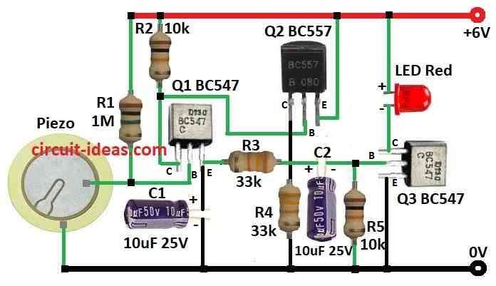
This is sound to light circuit which uses 3 transistors to make weak sound signal strong and turn LED light ON.
Piezo changes sound to electric signal.
Transistor Q1 first amplifiers make weak sound signal strong.
Capacitor C1 block DC and let AC sound go in.
Resistor R1 give proper current to Q1.
Capacitor C2 sends signal from Q1 to Q2 and blocks DC and passes AC.
Transistor Q2 second amplifier makes signal more strong.
Resistor R3 gives proper current to Q2.
Resistor R4 and R5 make voltage divider and sets switch level for Q3.
Transistor Q3 is a rectifier.
It change AC signal to pulse DC.
When signal is strong Q3 allow current to LED.
LED light up with sound, with more sound more light.
How to Build Sound to Light Converter Circuit using Piezo:
To build a sound to light converter circuit using piezo follow the steps:
- Q1 collector goes to positive through resistor R2.
- Q1 base connect to piezo.
- Q1 emitter goes to ground through capacitor C1.
- Q2 collector goes to ground through resistor R4.
- Q2 base connect to Q1 collector.
- Q2 emitter goes to positive.
- Q3 collector goes to positive through red LED.
- Q3 base connect to Q1 emitter through resistor R3.
- Q3 emitter goes to ground.
Circuit Working of Sound to Light Converter Circuit using Electret Mic:
Parts List:
| Category | Component | Quantity |
|---|---|---|
| Resistors (All resistors are 1/4 watt unless specified) | 10k | 2 |
| 470Ω | 2 | |
| 1M | 1 | |
| 4.7k | 1 | |
| Capacitors | Ceramic 100nF | 1 |
| Semiconductors | Transistor BC547 | 2 |
| Transistor BC557 | 1 | |
| LED Red 5mm 20mA | 1 | |
| Electret Mic | 1 |
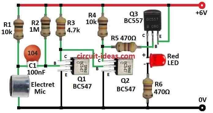
This is sound to light circuit using electret mic.
Electret mic change sound to small AC voltage.
Signal is weak and it needs amplifier to make strong for LED.
Q1 and Q2 amplifier are for common emitter which make weak signal strong.
Q3 is the emitter follower which gives more gain and changes high to low impedance for LED.
Capacitor C1 blocks DC and only passes AC sound signal.
It stop power supply DC from going to mic.
Resistors R1 to R6 set gain and bias for transistors.
R1 is the bias current for Q1
R2 & R3 are the voltage divider for Q1 base
R4 is the bias current for Q2
R5 is the voltage for Q2 base
R6 is the limit current for LED
LED is output.
More sound is more LED brightness.
Formulas:
To make amplifier for electret mic we need to understand transistor amplifier basics.
Transistor Amplifier with Common Emitter:
Voltage gain (Av) can be found by this formula:
Av = –RC / re
where:
- RC is resistor at collector
- re is small internal resistance at emitter
This help design simple mic amplifier.
Use formula to choose correct resistors and we can get the needed gain.
How to build Sound to Light Converter Circuit using Electret Mic:
To build a Sound to Light Converter Circuit using Electret Mic follow the below mentioned steps:
- Q1 collector goes to positive through R3
- Q1 base connect to C1
- Q1 emitter goes to ground
- Q2 collector goes to positive through R4
- Q2 base connect to Q1 collector
- Q2 emitter goes to ground
- Q3 collector goes to ground through red LED and R6 in series
- Q3 base connect to Q2 collector through R5
- Q3 emitter goes to positive of 6V battery
- Connect mic and R1 in series from positive to ground
Note:
- Be careful! making circuits can be risky.
- If anyone is new to electronic then learn well and stay safe before trying.
Conclusion :
Sound to Light Converter Circuit changes sound into light.
This circuit is fun way to learn electronics.
Simple ones flash with sound and big ones can make cool light shows or help people.
Now take tools and see sound in new way!
Leave a Reply