Simple Storm Detector Circuit is like small weather magic in box.
It can feel lightnings electric noise which shows storm is coming near.
This circuit uses one antenna to catch small signal in air like small radio.
But signal being weak it uses amplifier to make signal strong.
Sometimes it also uses special filter to remove bad noise, so only storm signal is available.
At end circuit send signal to speaker which makes sound when lightning come and shows on screen as wave line.
So when one hears thunder sound far away, can check with this circuit if storm really coming or not.
Circuit Working:
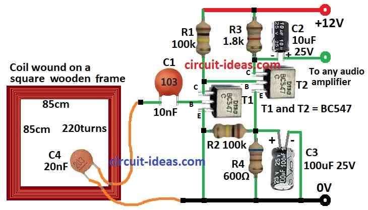
Parts List:
| Component Type | Description | Quantity |
|---|---|---|
| Resistors | 100k 1/4 watt | 2 |
| 1.8k 1/4 watt | 1 | |
| 600Ω 1/4 watt | 1 | |
| Capacitors | Ceramic 10nF | 1 |
| Ceramic 20nF | 1 | |
| Electrolytic 10µF 25V | 1 | |
| Electrolytic 100µF 25V | 1 | |
| Semiconductors | Transistors BC547 | 2 |
| Antenna Square wooden frame coil wound with 220 turns, 85x85cm | 1 |
This storm detector circuit is easy to make.
It has one sensitive amplifier and one antenna.
Both work together to find storm from far place.
Antenna is made by 220 turns of copper wire with enamel.
Wire is put on wooden square frame each side is 85 cm long.
Wire size is not very important one can use 0.4 mm wire its okay.
One capacitor is put with wire ends side by side.
This makes antenna work at 4 to 5 kHz frequency.
Antenna connect to amplifier using two wires twisted together.
The signal from this go to speaker or oscilloscope so one can hear or see storm signal.
Formulas:
When making storm detector circuit we must use electromagnetic signal to find things like lightning and thunder in sky.
To catch storm signal we have used resonance and amplifier in circuit.
Formula is:
f = 1 / 2π√(L * C)
where,
- L is coil inductance from wire on wooden frame antenna.
- C is capacitor value connected with coil side by side.
Amplification Gain:
Transistor amplifier make weak signal strong.
For that we have used the following formula:
Av = RC / re
where,
- RC is resistor on collector side.
- re is small inside resistance from transistor emitter.
Gain Av shows how much weak storm signal can be made big by circuit.
Note:
These formulas help one start building storm detector.
But one need to change values of parts little bit to make circuit work better and catch storm signal clearly.
How to Build:
To build a Simple Storm Detector Circuit we need to follow the below mentioned steps:
Prepare the Antenna:
- Take enameled copper wire and turn it 220 times around square wooden frame.
- Check the wire goes tight and even.
Add the Capacitor:
- Put one 20nF capacitor C4 with the two ends of the wire with parallel connection.
- This help antenna work in 4 to 5 kHz frequency.
- One can try other values if needed.
Connect Antenna to Amplifier:
- Use two wires twisted together to join antenna to amplifier input.
- Make connection strong and cover well with tape or insulator.
Connect Amplifier Output:
- Join amplifier output to audio amplifier or oscilloscope.
- This will help one to hear or see storm signal.
Power the Circuit:
- Give power to amplifier like it needs.
- Use good and steady power supply which is not too high or too low.
Test the Circuit:
- Turn ON the circuit and check what happen.
- If one uses oscilloscope see wave when storm is near.
- If one uses speaker hear sound when storm activity happen.
Make Adjustments:
- Try changing capacitor value or antenna a bit to make signal stronger.
- Try different setups to get better result.
Use the Circuit:
- When it works good one can use it to watch storm from far.
- Just look or listen to the output to know if storm is coming close.
Note:
- Be careful when working with electricity.
- Check all wire joints are safe and covered to stop any accident or damage.
Conclusion:
Simple Storm Detector Circuit is useful electronic tool.
It uses antenna, amplifier and sometimes tuning circuit to catch electromagnetic signals from storm.
It gives early warning when storm is coming.
This is good for people who like weather or do research on it.