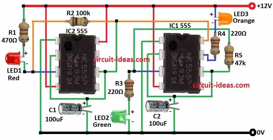
This project is Simple Traffic Signal Lights Circuit using IC 555.
It uses 555 IC and LEDs to show traffic signal lights in sequence.
The circuit is simple to build and parts are easy to find.
Circuit Working:
Parts List:
| Category | Description | Quantity |
|---|---|---|
| Resistors | 470Ω, 100k, 47k 1/4 watt | 1 each |
| 220Ω 1/4 watt | 2 | |
| Capacitors | Electrolytic 100μF 25V | 2 |
| Semiconductors | IC 555 | 2 |
| LED Red 5mm 20mA | 1 | |
LED Orange 5mm 20mA | 1 | |
LED Green 5mm 20mA | 1 |
Introduction about Traffic Signal Circuit:
This project make small traffic lights using two IC 555.
It copies real traffic light timing and maybe like in Australia.
When red light is OFF then IC2 gives power to IC1 and then green LED turns ON.
Then IC1 changes and orange LED turns ON and green LED is OFF.
After that IC2 stops IC1 and red LED turns ON again and the cycle repeat.
The circuit needs 9V to 12V power.
IC1 get little less voltage and LEDs connect to IC 555 directly in both high/low ways.
Power control is done at pin 8 and pin 3 does not work if LEDs are connected directly and so pin 7 is used because it connected to pin 3.
How Circuit Works:
Both ICs work in astable mode which means keep switching.
IC2 control power to IC1.
At start IC2s C1 capacitor discharges and pin 3 goes high and red LED turns OFF.
Same time IC2 give power to IC1 and green LED turns ON.
IC1s C1 charge to 2/3 Vdd and then orange LED turns ON and green LED turns OFF.
Then IC2s output fall after IC1s timer end with IC1 is off and red LED flashes.
Cycle restart as IC2s C1 capacitor discharge through R2 resistor.
IC2 decide big time cycle with R2 resistor and IC1 decide small time cycle with R5 resistor.
First time power ON looks different because both capacitors start from 0V and need time to charge.
Formulas:
Traffic Light Circuit Using IC 555:
IC 555 in astable mode can make simple traffic signal with 3 LEDs like red, orange (amber) and green.
It gives timing sequence to change lights one by one.
Formula for Frequency (f):
In astable mode frequency depends on resistor R1, R2 and capacitor C:
f = 1.44 / (R1 + 2R2) × C
- R1 and R2 are resistors
- C is timing capacitor
Duty Cycle D:
Duty cycle means how long output stay ON or OFF:
D = R2 / (R1 + 2R2)
Change R1, R2 and C to set timing for traffic lights as we need.
How to Build:
To build a Simple Traffic Signal Lights Circuit using IC 555 follow the below mentioned connections steps:
- Put all parts like in circuit diagram.
- Connect pin 1 of IC1 to ground.
- Connect pin 2 to pin 6 of IC1 and then to ground through C2.
- Connect pin 3 of IC1 to ground through R3 and greenLED2.
- Connect pin 4 of IC1 to +12V supply.
- Connect pin 6 to pin 3 of IC1 through R5.
- Connect pin 7 of IC1 to +12V through R4 and orange LED3.
- Connect pin 8 of IC1 to pin 3 of IC2.
- Connect pin 1 of IC2 to ground.
- Connect pin 2 to pin 6 of IC2 and then to ground through C1.
- Connect pin 3 of IC2 to +12V through R1 and red LED1.
- Connect pin 4 of IC2 to +12V.
- Connect pin 6 of IC2 between pin 3 of IC2 and pin 8 of IC1.
- Connect pin 8 of IC2 to +12V.
Conclusion:
This Simple Traffic Signal Lights Circuit using IC 555 is in astable mode to control traffic light timing.
Trick is to control power to second IC and use correct resistors.
At first power up lights act different because capacitors charges and after that it works fine.
Be safe and use correct parts and handle every parts carefully.