Small switch we call transistor is inside almost all electronic thing, but transistor cannot handle big power by itself.
So we have used Simple Transistor Relay Driver Circuit which is like a special adapter for transistor and this help small signal from transistor to control big relay switch.
Also, with this we can turn ON or OFF big power thing like light or motor using small weak signal and this idea is very important to know before starting any electronics work.
What is a Transistor Relay Driver Circuit:
Circuit that use transistor to control relay we call it transistor relay driver circuit, relay is electromechanical switch and it controls big power device using small power signal.
Further, small signal connects to transistor and transistor make it bigger and then this power connects to relay coil to turn it ON.
Circuit Working:
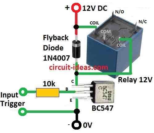
Parts List:
| Components | Values | Quantity |
|---|---|---|
| Resistors | 10k 1/4 watt | 1 |
| Semiconductors | Transistor BC547 | 1 |
| Flyback Diode 1N4007 | 1 | |
| Relay 12V | 1 |
First, the transistor becomes active when we apply a small voltage greater than 0.6 V to the base-emitter junction.
Also, this is important because it allow current to flow between collector and emitter and when transistor is active it work like a switch for the relay.
Now current can flow through relay coil.
Then this current make magnetic field and that close the relay switches from inside and then a big load can turn ON or OFF.
Moreover, when the relay turns OFF or the input voltage drops, the coil generates a reverse voltage (back EMF) and this back EMF can damage the transistor, so we should place a freewheeling diode across the relay coil.
Diode give safe path for this reverse voltage to go out and also we should use one resistor at transistor base which controls how much current goes in.
Set the base current correctly so the transistor operates properly and avoids damage.
Lastly, this all information helps to choose right parts and to be sure relay work properly.
Formula:
We can calculate base resistor value (Rb) for BJT transistor in current limiter circuit.
We will use this formula:
Vin = (Vs – 0.7) × HFe / Collector Current
where:
- Vin is voltage at transistor base which is usually between 0.7V and 1.2V
- Vs is power supply voltage
- HFe is transistor gain of DC current gain
- Collector Current max current allowed in collector
How to Build:
To build a Simple Transistor Relay Driver Circuit below mentioned are the steps to follow:
Steps:
- First, the circuit diagram shown above show transistor working in common emitter mode.
- Next, connect the relay coil between the positive supply (+V) and the collector of the transistor.
- Then use transistor in common emitter mode.
- After that, connect relay coil between positive supply and transistor collector.
- Also, give small voltage more than 0.6V to base emitter part of transistor.
- Finally, when transistor turn ON it will allow current to flow and relay will also turn ON.
Add Diode for Protection:
- Do not forget to put a freewheeling diode across relay coil as this will stop high voltage back EMF when relay turn OFF.
- Also, diode give safe path for back EMF to go.
- Hence, this will save transistor from getting damage and EMF will not go through collector emitter path.
Conclusion:
Learning about this Simple Transistor Relay Driver Circuit is very helpful as it give electronics hobby people an easy way to control big loads like lights or motors.
Also, it helps to understand more about how electronics work and by building this circuit and using formulas given, new learners can feel confident to start working with electronics.