This simple Two-Way Intercom Circuit let two places talk to each other like old home or office system.
Main parts of this circuit are:
Microphone: change voice to electric signal
Audio amplifier (LM386): make mic signal strong
Speaker: change strong signal back to sound
SPDT switch: choose talk or listen mode
Circuit Working:
Parts List:
| Category | Item | Quantity |
|---|---|---|
| Resistors | 10Ω 1/4 watt | 1 |
| 4.7k 1/4 watt | 1 | |
| 10k 1/4 watt | 1 | |
| Potentiometer 10k | 1 | |
| Capacitors | Ceramic 0.1μF | 1 |
| Ceramic 0.047μF | 1 | |
| Electrolytic 10μF 25V | 2 | |
| Electrolytic 1000μF 25V | 1 | |
| Semiconductors | IC LM386 | 1 |
| SPDT switch | 1 | |
| Electret Microphone | 2 | |
| 8Ω speakers | 2 |
Breadboard help make and test circuit easily.
LM386 chip make weak mic signal strong which is normal 20×, max 200×.
For max gain put capacitor between pin 1 and pin 8.
R2 control speaker volume and here in this article resistor 4.7k used.
For better volume try 1k to 100k resistor.
Strong signal from pin 5 goes to both speakers.
SPDT switch is used because both mics cannot boost same time.
Switch connects one mic to amplifier where only one person talk at a time like half duplex.
Move switch to choose which mic is active.
Formulas:
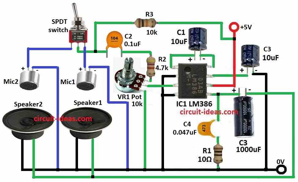
This circuit diagram shows how to make basic two-way intercom using IC LM386 with some calculations and explanation.
How to Calculate LM386 Gain:
Gain (Av) depends on capacitor C1 between pin 1 and 8.
Formula for gain:
Av = 1 + Rf / Rin
where,
- Rf is the resistance between pin 1 and 5 for that use potentiometer
- Rin is the resistance between pin 3 and ground
We can change Rf and Rin to get the gain we want.
Example:
If Rf = 10k and Rin = 10k
Then gain = 1 + 10k / 10k = 2
Choose right values for resistor, capacitor and potentiometer based on what our intercom needs like how loud it should be, what sound range it should be and power level.
Check LM386 datasheet and notes to help choose best parts.
How To Build:
To build a Two-Way Intercom Circuit follow the below mentioned steps for circuit connections:
- Collect all parts shown in the diagram.
- Connect pin 1 to pin 8 of IC1 LM386 with capacitor C1.
- Connect pin 2 and pin 4 of IC1 to ground.
- Connect pin 3 of IC1 to one leg of 10k potentiometer VR1.
- Connect pin 5 of IC1 to one side of speaker 2.
- Connect pin 6 of IC1 to +5V power.
- Connect pin 7 of IC1 to capacitor C3 and then to ground.
- Connect capacitor C4 and resistor R1 in series between pin 5 and ground.
- One leg of VR1 to middle pin of SPDT switch through capacitor C2 and resistor R2
- Second leg of VR1 to pin 3 of IC1
- Third leg of VR1 to ground
- First pin of SPDT switch to positive of MIC2
- Third pin of SPDT switch to positive of MIC1
- Negative of both MICs to ground
- One leg of speaker1 and speaker2 to ground
- Other leg of both speakers to pin 5 of IC1
Safety Tips:
- Use correct voltage and current for battery or power supply.
- Do not use power more than circuit can handle.
- Handle batteries safely and dispose as per local rules.
- Follow these steps to avoid electric problems and enjoy safe building.
Conclusion:
This Two-Way Intercom Circuit helps two people talk.
It uses IC LM386 to make mic signal strong.
SPDT switch ensures only one person talks at one time like walkie-talkie.
It is a good project to learn about amplifier and signal control.
Always follow safety rules while working with circuits.
References:
A Cost-Effective Two-Way Household Wireless Door Intercom System