This circuit makes LED glow slowly and then fade slowly which looks like breathing effect.
It uses simple parts like only resistor capacitor and transistor and with no microcontroller.
This Simple Up Down Fading LED Circuit is good for beginners and easy to build on breadboard.
This type of circuit can be used in shopping malls, home and for security applications.
Circuit Working:
Parts List:
| Component | Specification | Quantity |
|---|---|---|
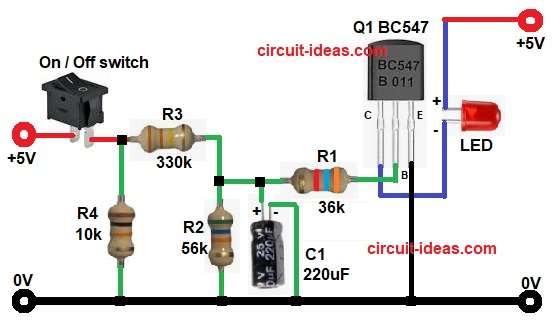
| Resistors (All resistors are 1/4 watt) | 330k, 56k, 36k, 10k | 1 each |
| Capacitor | Electrolytic 220uF 25V | 1 |
| Semiconductors | Transistor BC547 NPN | 1 |
| LED any 5mm | 1 | |
| Switch On / Off | 1 | |
| Power Supply 5V DC | 1 |
The circuit works at 5 volt power supply and uses a resistor capacitor network.
R2 and C1 make timing where voltage on capacitor slowly increases.
When capacitor voltage increases then base of transistor Q1 gets voltage through R1.
Transistor starts to turn ON slowly and LED glows bright slowly.
When power is OFF or capacitor discharges then voltage falls slowly and transistor switches OFF slowly and LED fades slowly.
R3 and R4 create small voltage supply for charging capacitor.
R1 limits base current of transistor as Q1 is NPN BC547 which controls LED current.
Formula:
Formula for charging time constant:
tau = R x C
where,
- tau means time constant of the RC circuit.
- R is R2 the charging resistor in series with the capacitor
- C is C1 the electrolytic capacitor that stores charge
How to Build:
To build a Simple Up Down Fading LED Circuit follow the below steps:
- Take all the parts as shown in circuit diagram.
- Transistor Q1 emitter goes to ground.
- Collector goes to LED negative terminal.
- LED positive terminal goes to positive supply.
- Base goes to junction of R1 and capacitor C1 positive.
- And capacitor negative pin goes to ground.
- R2 goes between capacitor C1 positive pin and GND.
- R4 goes between switch and resistor R3 and GND.
Conclusion:
This is very Simple Up Down Fading LED Circuit.
It uses resistors and capacitor timing and transistor gives smooth brightness change.
It is good for learning RC circuits and is easy to expand for many LEDs by using more transistors.
Leave a Reply