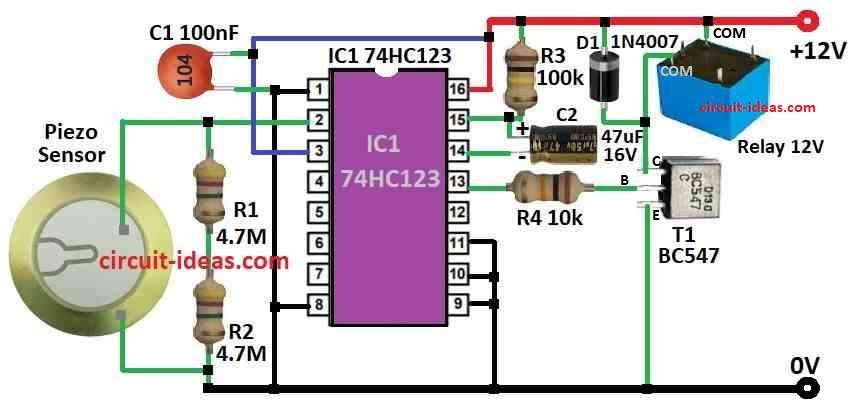
Simple Vibration Sensor Circuit is like small touchy friend for electronics.
It is felt when we shake or quick move happen and then it sends the electric signal.
This is good for use in thief alarm to feel someone come in or for earthquake to feel ground move.
Also we can use it in factory machine to check if all is working okay.
Circuit Working:

Parts List:
| Type | Description | Quantity |
|---|---|---|
| Resistors | 4.7M 1/4 watt | 2 |
| 100k 1/4 watt | 1 | |
| 10k 1/4 watt | 1 | |
| Capacitors | Ceramic 100nF | 1 |
| Electrolytic 47µF 16V | 1 | |
| Semiconductors | IC 74HC123 | 1 |
| Transistor BC547 | 1 | |
| Diode 1N4007 | 1 | |
| Piezo sensor | 1 | |
| Relay 12V | 1 |
Using one simple piezo electric sensor we can make a working impact sensor which can feel hits or shakes on doors, windows, showcase or other flat places.
This sensor uses one “unimorph” plate it is like one piezo disk stick with metal disk.
When something is hit or shake sensor make voltage and this voltage depends on how strong the hit is.
Like for 60G hit or it can make around 2 volt.
Whole setup uses low voltage and low current.
The sensor send signal to special chip IC1 which is monostable multivibrator and this chip then turn ON a transistor T1.
This transistor has open collector output and it can connect to alarm or other circuit to do something when sensor feel a hit.
When sensor feel the impact the chip turn ON the transistor for some time and how long it stay ON depends on resistor R3 and capacitor C2 values in circuit.
The IC1 chip is 74HC123 and it is fast CMOS type which is made strong to handle static or extra voltage.
It has two trigger inputs one for going up and other one for going down but here we can only use one the positive edge one of pin 2.
After trigger the output stays ON for time set by R3 and C2 and then goes OFF again.
Formula:
For 74HC123 chip we can imagine the output pulse time (tW) using this common formula:
tW = 1.1 × Rx × Cx
where:
- tW is how long output which stays ON in seconds
- Rx is resistor value in ohms
- Cx is capacitor value in farads
Note:
Real output time will be little different it can change because of temperature or chip quality.
How to Build:
To build a Simple Vibration Sensor Circuit follow the below mentioned circuit building steps:
- First take all parts we need for this sensor design.
- Now connect the ceramic piezo shock sensor in the circuit.
- Wire it correct way and check sensors datasheet to know where to connect the wires.
- Put the 74HC123 chip IC1 in the circuit.
- Connect pins right as shown in its datasheet it must connect to other parts like sensor, power, etc.
- Now connect NPN transistor like BC547 in the circuit.
- This transistor gets signal from IC1 and turn ON.
- Put resistors R1, R2, R3, R4 and capacitors C1, C2 in place.
- These parts help in timing and how the IC1 works.
Give power:
- Connect 12V power to the whole setup.
- Be sure all parts can handle 12V safely.
Try it out:
- Tap or shake the piezo sensor a little.
- IC1 should send signal to transistor and if working then transistor can turn ON alarm or switch circuit.
Make changes if needed:
- If sensor is too sensitive or not enough we can change resistor or capacitor values.
- Try other values to get best result.
Optional connect to alarm:
- We can connect transistor output to outside alarm or switch to do more action when sensor feel impact.
Finish setup:
- After test adjust and fix all parts properly.
- Be sure there are no loose wire or open connection.
Note:
- Be careful while working with electric things like battery or soldering this can cause danger
- Only try this if you know how to work safe with electronics.
Conclusion:
Simple Vibration Sensor Circuit is important part in many things where we feel shaking or sudden move.
It can change vibration into electric signal.
This way it can help to check and alert or turn ON alarm when something moves or shakes.
It make place more safe and secure in many uses..