
Wireless RF Network Cable Tester Circuit is like X-ray for internet wire, which can catch radio signal inside cable like ethernet, modem or satellite TV but there is no need to touch the wire.
Also, it is very easy to use for checking cable working or not; for that just hold tester near the wire and it will show if signal is there or not.
Therefore, there is no need to unplug or fight with messy cable as this small circuit will help one to check fast and easily.
Circuit Working:
Parts List:
| Components | Values | Quantity |
|---|---|---|
| Resistors | 100k, 1k, 3.9M, 100Ω (all 1/4 watt) | 1 each |
| Capacitors | Ceramic 0.1µF | 2 |
| Semiconductors | IC 3140 | 1 |
| Diode BAT43 | 1 | |
| LED any 5mm 20mA | 1 | |
| Coil 10 turns, 22SWG, 5mm diameter air core | 1 | |
| Antenna | 1 | |
| Battery 9V | 1 |
To begin with, this is wireless cable tester which helps to find if RF signal inside network cable; as there is no need for tester to touch the cable it can catch signal from 2 feet away.
Furthermore, this circuit is good for ethernet, modem or dish TV cable.
When signal is there LED light turns ON.
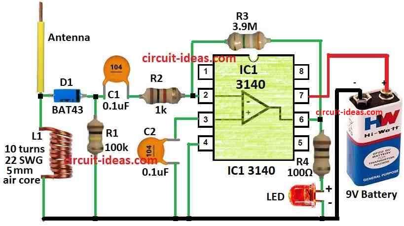
Tester has two part: one is front part and other is signal amplifier; front side has RF detector then signal goes to amplifier and detector part has coil L1, diode D1, capacitor C1 and resistor R1, R2.
Coil L1 is a small 5 mm round coil with 10 turns of copper wire, diode D1 is a fast Schottky diode and capacitor C1 blocks extra signals to prevent problems.
Amplifier uses IC 3140 chip which is fast chip and uses very low current, as it works from 5V to 36V.
Also, when the long antenna rod comes near, coil L1 catches the signal and diode D1 sends the signal to IC1; then IC1 uses resistor R3 for feedback to make the weak signal stronger.
When signal comes IC1 gives output high and LED lights up which means signal is inside the cable.
Formulas:
Here, are some formulas for making resonant circuit and antenna in RF system:
LC Resonant Frequency:
f = 1 / 2π√LC
where,
- L is the coil inductance
- C is the capacitor value
Antenna Length for Half Wave Dipole:
L = c / 2f
where,
- L is the antenna length
- c is the speed of light which is about 3 x 10⁸ m/s
- f is the signal frequency
Bandwidth of LC Circuit:
BW = f₀ / Q
where,
- f₀ is the center frequency
- Q is the quality of LC circuit
For full design and need for more calculation it also depends on what frequency and modulation one uses.
How to Build:
To build a Wireless RF Network Cable Tester Circuit we need to follow the below mentioned assembling steps:
- First, one side of coil L1 connects to the place where resistor R1 and R2 join and other side of coil L1 connects to diode D1 anode side
- Then diode D1 cathode side connects to pin 2 inverting input of IC 3140.
- Capacitor C1 connect between pin 6 output and pin 2 of IC.
- Now resistor R3 also connect between pin 6 and pin 2 of IC 3140.
- Pin 3 non-inverting input of IC 3140 connect to ground.
- Then LED with one resistor current limit go between pin 6 and positive power (V+).
- Power supply: connect +V to pin 8 and -V to pin 4 of IC3140.
- Lastly, telescopic antenna connect to coil L1.
Note:
- Be sure circuit is build properly and all wire and parts must be tight and safe and if needed change the parts values to get better signal to detect and for sensitivity.
Conclusion:
To conclude, Wireless RF Network Cable Tester Circuit is very useful tool, it can check RF signal in cable with fast and easy way without a need to touch the cable.
Finally, this type of circuits are very good for technician and installer who work with network wire.