In this post halogen lamp draws very high current at switch ON, then cold filament resistance is very low and this causes sudden inrush current.
Lamp life becomes short, then this circuit protects lamp and it also protects outside fuse and switch indirectly; therefore, Soft ON Circuit for 12V Halogen Lamp reduces this problem.
Lamp voltage rises slowly which turns ON smoothly and its life increases.
Circuit Working:
Parts List:
| Components | Values | Quantity |
|---|---|---|
| Resistors (All resistors are 1/4 watt unless specified) | 10k | 2 |
| 100k, 390Ω, 2.7Ω 5 watt | 1 each | |
| Capacitors | Electrolytic 220uF 25V | 2 |
| Semiconductors | Transistor BC547 | 2 |
| Optocoupler / Opto-Triac S202DS4 | 1 | |
| Bridge Diode 1N4148 | 4 | |
| 12V 50W Halogen Bulb | 1 |
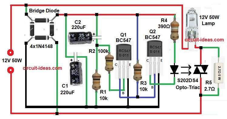
To begin with, the circuit receives a 12V AC, 50W supply, then the bridge rectifier converts the AC voltage into DC, and the capacitors smooth the DC voltage.
Then C1 and C2 capacitors charge slowly and this creates time delay; after that at power ON C2 is empty with Q1 transistor stays OFF and Q2 transistor is also OFF.
Opto-triac does not conduct and lamp gets very low voltage, then with time C2 charges through R1 and R2 and base voltage of Q1 increases slowly.
Now Q1 turns ON slowly and Q2 also turns ON and then current flows through R4 to opto-triac LED and trough this opto-triac triggers slowly.
After that, the triac conduction angle increases, causing the lamp voltage to rise smoothly and after a few seconds, the lamp reaches full brightness while the circuit limits the inrush current and protects the lamp filament.
Formulas:
Formula for rectified DC voltage:
Vdc = Vac x 1.414 – diode drop
where,
- Vdc means DC voltage after rectifier.
- Vac means AC RMS input voltage.
- 1.414 is square root of 2 value.
- Diode drop means voltage loss in rectifier diodes.
How to Build:
To build a Soft ON Circuit for 12V Halogen Lamp follow the below steps:
- First, take all the parts as shown in circuit diagram.
- Next, bridge rectifier positive pin goes to C1 and C2 positive and negative pin goes to ground line.
- Also, rest two pins connect to 12V 50 watt
- Now BC547 Q1 emitter pin connect to ground, base pin connect to R2 and C2 junction and collector pin connect to junction of base of T2 and resistor R3
- Then T2 BC547 emitter pin goes to ground, base pin connect from Q1 collector and R3 and collector pin goes to R4 and opto-triac LED.
- After that, opto-triac S202S04 input LED pins connect to R4 and T2 collector and then output triac pins connect in series with lamp
- Furthermore, connect the lamp to the AC line through the opto-triac and finally, connect resistor R5 in parallel with the opto-triac.
Conclusion:
To conclude, this Soft ON Circuit for 12V Halogen Lamp is simple and its parts are easily available and it protects halogen lamps.
Also, reducing the inrush current increases the lamps lifespan, making this circuit ideal for 12V halogen lighting systems.

Leave a Reply