
This Switch Selectable Four Frequency Pulse Generator Circuit is a simple astable oscillator that uses the popular 555 timer IC in astable mode and also users can change the output frequency in four steps by pressing the switch to select different capacitors.
Here, output is the square wave signal and it works in astable mode, so it produces continuous pulses; also supply voltage is 4.5V to 15V and hence, it can run from battery or DC adapter.
Moreover, this circuit uses low cost components, making it easy to build and well suited for students and hobbyists.
Circuit Working:
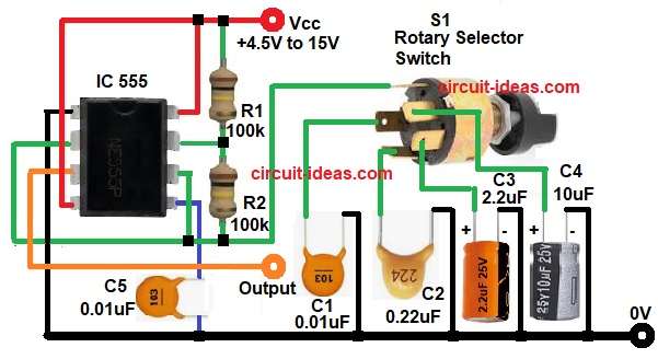
Parts List:
| Components | Values | Quantity |
|---|---|---|
| Resistors | 100k | 2 |
| Capacitors | Electrolytic 2.2uF 25V, 10uF 25V | 1 each |
| Ceramic 0.01uF | 2 | |
| Ceramic 0.22uF | 1 | |
| Semiconductors | 555 Timer IC | 1 |
| Single-Pole, Four-Position Rotary Selector Switch | 1 | |
| Power Supply 4.5V to 15V DC | 1 |
At first, the 555 IC connected in astable mode and in this mode it does not need external trigger, but it continuously charges and discharges capacitor; also R1 and R2 control charging and discharging time and selected capacitor decides frequency range.
When power is ON the capacitor starts charging through R1 and R2 and when voltage across capacitor reaches 2/3 of Vcc then internal comparator resets flip flop and then output goes LOW.
After that the capacitor discharges through R2 and when capacitor voltage drops to 1/3 of Vcc then output becomes HIGH again.
Thus, this process repeats continuously and hence, square wave produced at pin 3.
Now, if we change capacitor using switch S1 then charging time changes and therefore, frequency changes.
Small capacitor gives high frequency and large capacitor gives low frequency, C5 connected to control pin 5 which reduces noise, so output becomes stable.
Formulas with Calculation:
Frequency formula:
f = 1.44 / ((R1 + 2R2) × C)
Since R1 = 100000
R2 = 100000
R1 + 2R2 = 100000 + 200000
R1 + 2R2 = 300000 ohm
So the formula becomes:
f = 1.44 / (300000 × C)
Now calculate for each capacitor.
Step 1:
C1 = 0.01uF
Convert to Farad:
0.01uF = 0.01 × 10^-6
C = 1 × 10^-8 F
f = 1.44 / (300000 × 1 × 10^-8)
= 1.44 / 0.003
f = 480 Hz
Step 2:
C2 = 0.22uF
0.22uF = 0.22 × 10^-6
C = 2.2 × 10^-7 F
f = 1.44 / (300000 × 2.2 × 10^-7)
= 1.44 / 0.066
f = 21.8 Hz
Step 3:
C3 = 2.2uF
2.2uF = 2.2 × 10^-6 F
f = 1.44 / (300000 × 2.2 × 10^-6)
= 1.44 / 0.66
f = 2.18 Hz
Step 4:
C4 = 10uF
10uF = 10 × 10^-6
C = 1 × 10^-5 F
f = 1.44 / (300000 × 1 × 10^-5)
= 1.44 / 3
f = 0.48 Hz
So frequency changes from around 0.48 Hz to 480 Hz.
How to Build:
To build a Switch Selectable Four Frequency Pulse Generator Circuit follow the below connection steps:
- Start, the circuit first by gathering all the circuit parts.
- Then start with IC 555 pin 1 which goes to Ground.
- After that, pin 2 of IC join with pin 6 of IC and connect to junction of R2 and switch of selected capacitors one end.
- Now pin 3 connect to the output square wave.
- Further, pin 4 and pin 8 of IC connect directly to Vcc of +4.5V to +15V supply.
- Also, pin 5 connect capacitor C5 and ground.
- Next, pin 7 connect between R1 and R2 resistor.
- Finally, connect switch S1 4 pins with one capacitor each at one end and other end goes to ground.
Conclusion:
To conclude, this Switch Selectable Four Frequency Pulse Generator Circuit is a simple and useful project because it uses a 555 timer in astable mode and allows users to change the frequency easily by selecting a different capacitor.
Moreover, this circuit covers a wide frequency range, from low to high frequencies, making it suitable for beginners, students and hobby projects; users can also modify the circuit by changing the resistor and capacitor values to obtain additional frequency ranges.
Thus, this circuit is easy, practical and reliable for basic pulse generation work.