This small Temperature Controlled LED Circuit can feel the heat!
When place near warm thing, it sense temperature and LED glow.
It work very simple using one diode and one transistor only.
No microcontroller, no sensor IC, just few parts.
We can build it easy at home and see how heat make light turn ON.
It is fun and good for learning basic electronics.
Circuit Working:
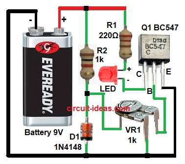
Parts List:
| Component Type | Value / Part Number | Quantity |
|---|---|---|
| Resistors | 220Ω 1/4 watt | 1 |
| 1k 1/4 watt | 1 | |
| Preset 1k | 1 | |
| Semiconductors | Transistor BC547 | 1 |
| LED Red | 1 | |
| Diode1N4148 | 1 | |
| Battery 9V | 1 |
The diode 1N4148 work like small temperature sensor.
When heat goes high the diode voltage become little less.
This make change in base of transistor Q1 BC547.
When base get enough voltage then transistor start working.
Then current go through LED and LED turn ON.
When temperature goes down again then diode voltage become more.
Then base current become less and LED goes OFF.
Formulas:
Voltage across diode = 0.7V at room temperature.
For every 1°C rise the voltage drops by about 2 mV.
So for 10°C rise the drop = 10 × 0.002 = 0.02V.
This small drop changes base bias of transistor.
Base emitter voltage VBE = 0.7V (approx).
Collector current IC = β × IB
If transistor gain β = 100, and base current IB = 20µA
Then IC = 100 × 20µA = 2mA.
This current is enough to light the LED through R1.
How to Build:
To build a Temperature Controlled LED Circuit follow the below steps for connection:
- Take all the parts as shown in circuit diagram.
- Emitter is connected to ground.
- Collector goes to LED and resistor R1.
- Base is connected to junction of D1 diode, R2 and VR1 preset.
- Battery positive connected to R1 and R2 and negative to ground.
Conclusion:
This Temperature Controlled LED Circuit can feel heat and make LED glow when hot come.
It very simple and cheap and good for small electronic learning.
We can move preset VR1 to change when LED start to glow.
It help us see how diode and transistor behave with heat.
Leave a Reply