LED displays are used in many small electronic devices and normally we need a transformer power supply, but however transformer makes the circuit big and costly.
Therefore, a capacitor power supply is a good alternative which is small and is with low cost and is easy to build.
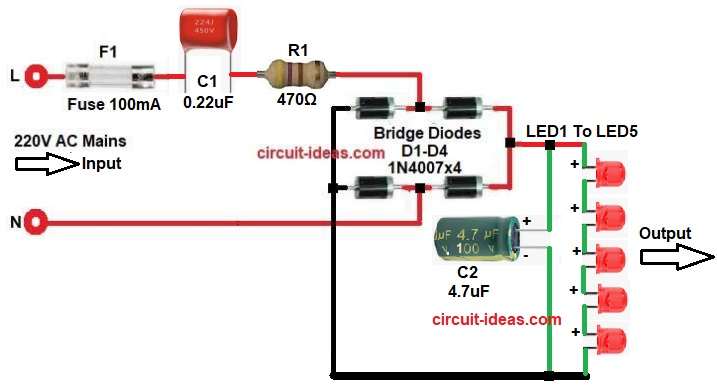
In this circuit a capacitor dropper supply is used and it converts 220V AC to low voltage DC and then five LEDs are connected in series to create a simple LED display.
This Transformerless LED Display Circuit using Capacitor Dropper is useful for indicator panels, decorative lights and simple display boards.
Circuit Working:
Parts List:
| Components | Values | Quantity |
|---|---|---|
| Resistor | 470Ω 1/4 watt | 1 |
| Capacitors | Polyester 0.22uF 450V | 1 |
| Electrolytic 4.7uF 100V | 1 | |
| Semiconductors | 1N4007 Bridge Diodes | 4 |
| Any color LED 5mm | 5 | |
| Fuse 100 mA 250V | 1 | |
| AC Input 220V AC | 1 |
This circuit uses a transformerless power supply and therefore it is directly connected to 220V AC mains, because of this the circuit can be dangerous if handled carelessly.
In the above diagram, 220V AC power enters the circuit through fuse which protect the circuit from overcurrent and the phase line passes through capacitor C1, then this capacitor C1 works as a current limiter which drops the AC current and therefore, the circuit does not require a transformer.
Next, resistor R1 is connected in series which protects the circuit from sudden surge current.
After that AC voltage goes to a bridge rectifier which is made using four diodes D1-D4 and these diodes convert AC voltage into pulsating DC voltage.
Then capacitor C2 is connected across the output and this capacitor smooths the DC voltage.
Finally, the filtered DC voltage powers the LED chain and all five LEDs are connected in series and therefore, current flows through the LED string and as a result all LEDs glow.
Formulas with Calculation:
Below is the capacitor dropper current formula:
I = V / Xc
where,
- I is the current in ampere
- V is the AC voltage
- Xc is the capacitive reactance
Capacitive reactance formula:
Xc = 1 / (2 * pi * f * C)
where,
- f is the AC frequency
- C is the capacitor value in farads
Example calculation as per the circuit:
C = 0.22uF
f = 50Hz
Xc = 1 / (2 * 3.14 * 50 * 0.22 * 10^-6)
Xc approximately = 14470 ohm
Current calculation:
I = 220 / 14470
I approximately = 0.015A
So output current is about 15mA and this current is suitable for operation in the circuit.
How to Build:
To build a Transformerless LED Display Circuit using Capacitor Dropper following are the connection steps:
- First, gather the circuit parts as in circuit diagram above.
- Then connect 220V AC phase line to one terminal of capacitor C1.
- Connect the second terminal of C1 to resistor R1.
- Connect the other side of resistor R1 to the bridge rectifier input.
- Connect bridge diode one end to positive of capacitor C2 output
- Connect one end of diode to Neutral line N and one end of diode to negative output.
- Connect capacitor C2 across the DC output with positive pin of C2 to positive output.
- Negative pin of C2 to negative output.
- Connect five LEDs in series.
- Connect LED1 anode to positive output.
- Connect LED1 cathode to LED2 anode.
- Connect LED2 cathode to LED3 anode.
- Connect LED3 cathode to LED4 anode.
- Connect LED4 cathode to LED5 anode.
- Connect LED5 cathode to negative output.
- Now power the circuit with 220V AC all the LEDs will glow.
Important Warning:
- This circuit is transformerless and therefore, it is directly connected to 220V AC mains.
- One should be careful while designing and testing this type of circuit.
- Do not touch the circuit when power is ON, because High voltage may cause electric shock.
- If possible add a fuse at the AC input for extra protection.
- This circuit is recommended for experienced electronics users and beginners should test it carefully under supervision.
Advantages of capacitor dropper power supply circuit:
- First advantage is of low cost, as the circuit is not using transformer, so overall cost becomes very low.
- Second advantage is of small size, capacitor and diodes need very little space, because of this circuit becomes compact.
- Another advantage is of simple construction, circuit uses very few components and so it is easy to build and also easy to repair.
- Power consumption is also low and therefore, it is good for small LED indicator circuits.
- Because of these reasons capacitor dropper circuits are widely used in LED indicators, night lamps and small display panels.
Disadvantages of the capacitor dropper power supply circuit:
- Main disadvantage is safety, as the circuit is directly connected to 220V AC mains, which is dangerous and can kill if touched when circuit is ON.
- Another limitation is low output current, capacitor dropper supply gives only small current and therefore, it is not suitable for high power devices.
- Voltage regulation is not good, as the output voltage may change if load changes.
- Also this power supply is not isolated from AC line, so it should not be used in circuits where user may touch the circuit.
- Because of these reasons this circuit is mostly used only for small indicator applications.
Conclusion:
This Transformerless LED Display Circuit using Capacitor Dropper is simple and is with low cost, as it uses a capacitor dropper power supply instead of a transformer.
Therefore, the circuit becomes small and economical and also it uses very few components which are easily available in market.
This circuit is useful for indicator lights, display panels and small lighting projects.
However, safety is very important because the circuit works directly with AC mains which can be dangerous and can even cause death in some conditions.
Leave a Reply