Reed switch is small switch which works with magnet.
When wire is near it has current and it makes magnetic field.
This magnetic field make reed switch turn ON or OFF depends how it is made.
It help to know if current is there.
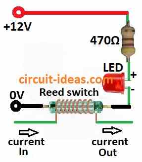
Circuit Working:
Parts List:
| Component Type | Description | Quantity |
|---|---|---|
| Resistor | 470Ω 1/4 watt | 1 |
| Semiconductors | Reed switch (see the text) | 1 |
| LED any 5mm 20mA | 1 |
In this setup we have used reed switch with LED and resistor to show if current is flowing in the circuit.
Reed switch needs around 10 to 100 AT ampere turns.
This means current in wire x number of coil turns.
Smaller AT value means reed switch is more sensitive.
For example In car headlight each bulb takes 7A or 8A at 12V.
So for 50 AT reed switch we need 7 or 8 wire turns to sense it properly.
If one bulb stop working and current goes down switch opens its contact.
Formulas and Calculations:
From this circuit we can use formula to find current:
I = V / R
where:
- I is current in amps A
- V is voltage in volts
- R is resistance in ohms Ω
In this circuit we have 12V and 470Ω so we can use this formula with calculation:
I = 12V / 470Ω = 0.0255 A or 25.5 mA
About 2 volts drop on LED so LED current is:
I = 2V / 470Ω = 0.0043 A or 4.3 mA
Note:
Reed switch current monitor is fast and simple way to check if current is present.
It can be used in many places like machines, alarm and security systems.
How to Build:
To build a Reed Switch as a Current Monitor Circuit we need to follow the steps mentioned below:
Gather Parts:
- We need one reed switch, one LED one resistor value depends on LED brightness and a battery or power source.
Connect Reed Switch:
- Put reed switch in series with the circuit we want to watch.
- Place it so it can open or close when current flows.
Add LED and Resistor:
- Connect LED in parallel with the reed switch.
- Put resistor in series with LED to stop too much current and protect LED.
Test Circuit:
- Turn ON the power and check if it works.
- LED should glow when current flows.
Install and Use:
- If circuit works fine install it where we want and use it to check current.
Note:
- Be careful with electricity if not sure ask help from an expert or electrician.
Conclusion:
Using a Reed Switch as a Current Monitor Circuit is easy and works well.
Reed switch reacts to magnetic field made by current so it can open or close when current flows.
This helps in checking and controlling current in different uses.
The setup is simple and we can change its sensitivity so it is useful for many current monitoring jobs.
References:
Circuit to turn microcontroller on when reed switch state changes (to monitor door lock state)
Leave a Reply