A 0-15V 3A Adjustable Power Supply Circuit gives adjustable DC voltage output from 0 volt to 15 volt and we use this circuit in electronic testing, small lab work, school projects and repair work, also this circuit helps us power many low-voltage devices safely.
In this circuit, the LM350 voltage regulator IC controls the output voltage, by rotating the potentiometer, we can increase or decrease the voltage easily and therefore, this circuit is simple, low cost and very useful for beginners.
Circuit Working:
Parts List:
| Components | Values | Quantity |
|---|---|---|
| Resistors | 270Ω, 820Ω | 1 each |
| 2.2k | 1 | |
| Potentiometer 5k | 1 | |
| Capacitors | Electrolytic 2200uF 25V | 1 |
| Electrolytic 22uF 25V | 2 | |
| Ceramic 0.1uF | 1 | |
| Semiconductors | IC LM350 Voltage Regulator | 1 |
| Heatsink for IC LM350 | 1 | |
| Diode 1N4007, 1N5402 | 2 each | |
| Bridge Diodes 6A | 4 | |
| Any standard LED | 1 | |
| Transformer primary 220V AC, secondary: 0V-12V 3A | 1 | |
| Fuse 0.5A | 1 | |
| On-Off switch | 1 |
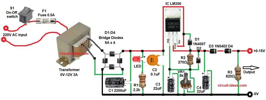
In the above circuit diagram, the 220V AC mains supply enters through a fuse and ON/OFF switch connected to the transformer primary, the fuse protects the circuit from overload and short circuit and the switch safely turns the power supply ON and OFF.
Next, the transformer steps down the voltage to 12V AC and then the rectifier diodes convert AC into DC.
After that, the filter capacitor smooths the output voltage and the C1 capacitor works as the main filter capacitor as it smooths the rectified DC voltage and reduces ripple before it enters the LM350 regulator IC.
The 0.1uF ceramic capacitor helps remove high-frequency noise and the 22uF capacitors improve output stability as they also make the voltage more smooth.
After that, the LM350 regulator IC with the VR1 potentiometer adjusts the voltage from 0V to 15V and the 270 ohm, 820 ohm and 2.2k resistors help set the output voltage range as they also keep the regulation stable.
Finally, the LED works as power ON indicator and the regulated DC output is available at the output terminals for powering electronic circuits.
How to Build:
To build a 0-15V 3A Adjustable Power Supply Circuit follow the below connection steps:
- Start, the circuit by collecting all the components as shown in diagram above.
- First, connect the transformer primary through the fuse and switch.
- Then connect the transformer secondary output to the bridge rectifier AC input terminals.
- After that connect the positive output of the rectifier to the positive terminal of C1 capacitor and connect the negative terminal of C1 to ground.
- Next, connect the LED and resistor R1 in series between the positive rectifier output and ground.
- After that connect capacitor C2 between the input pin of the IC and ground.
- Connect the adjust pin of the IC to ground through capacitor C3.
- Then connect resistor R2 and VR1 from the output pin of the IC to ground.
- Connect diode D1 anode to the output pin and connect its cathode to the input pin of the IC.
- After that connect the cathode of diode D2 to the output pin and connect the anode of D2 between resistor R2, VR1 and the adjust pin of the IC.
- Then connect the positive terminal of capacitor C4 to the output pin and connect the negative terminal of C4 to ground.
- Connect diodes D3 and D4 from the IC output pin to the 0–15V output terminal.
- Lastly, connect resistor R3 between the 0–15V output and ground.
Conclusion:
To conclude, the 0-15V 3A Adjustable Power Supply Circuit is very simple and useful for beginners as well as technicians.
Moreover, the LM350 IC makes voltage adjustment easy and stable and therefore, this circuit is perfect for testing and powering small electronic devices.
Leave a Reply