This circuit is a simple and useful DC to DC step-up converter built around the LM2577-ADJ IC and the main purpose of this circuit is to increase a low DC input voltage into a higher regulated DC output voltage.
Therefore, we can use it in battery-powered projects, automotive electronics, portable devices, LED drivers and other applications where higher voltage is needed from a lower source.
Meanwhile, the LM2577 is a switching regulator IC specially designed for boost converter applications which works with minimum external components and gives good output regulation.
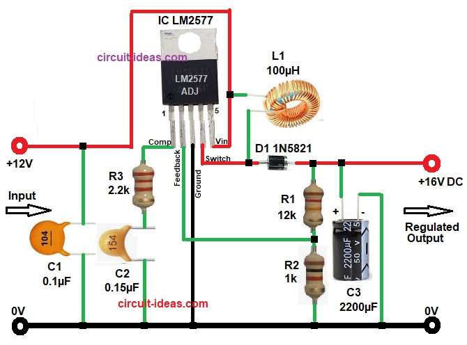
Hence, this 12V to 16V Adjustable DC to DC Step-up Converter Circuit accepts a 12V DC input and boosts it to a regulated 16V DC output by using the LM2577 IC and a feedback resistor network.
The LM2577 IC supports boost, flyback and forward converter topologies and uses an internal 1.23V reference for voltage control.
Circuit Working:
Parts List:
| Components | Values | Quantity |
|---|---|---|
| Resistors | 12k, 1k, 2.2k 1/4 watts | 1 each |
| Capacitors | Electrolytic 2200µF 50V | 1 |
| Ceramic 0.1µF, 0.15µF | 1 each | |
| Semiconductors | Schottky diode 1N5821 | 1 |
| Wire coil inductor 100µH | 1 | |
| IC LM2577-ADJ | 1 |
The above circuit works on the boost converter principle.
First, when DC supply enters the input terminal the capacitor C1 filters the input noise and stabilizes the supply line and the input voltage then goes to pin 5 of the LM2577 which is the Vin pin.
Next, inside the IC an internal switching transistor turns ON and OFF at around 52kHz.
During the ON time the IC stores energy in the 100uH inductor and current flows from the input supply through the inductor and into the IC switch pin.
After that, during the OFF time the magnetic field in the inductor collapses and releases stored energy and this energy passes through diode D1 to the output capacitor C3 and load, because of this action, the output voltage becomes higher than the input voltage.
Moreover, Schottky diode is important because it gives low forward voltage drop and fast switching response.
Meanwhile, capacitor C3 smooths the boosted DC voltage and reduces ripple at the output.
In addition, the feedback network made by R1 and R2 sends a divided voltage back to pin 2 which is the(feedback pin.
Finally, the IC compares this voltage with its internal 1.23V reference and adjusts switching duty cycle to keep the output stable.
Formulas with Calculation:
Output Voltage Formula:
Vout = 1.23 × (1 + R1 / R2)
where:
- Vout is output voltage
- R1 is upper feedback resistor
- R2 is lower feedback resistor
- 1.23V is the internal reference voltage of LM2577
Calculation for this circuit:
Vout = 1.23 × (1 + 12000 / 1000)
Vout = 1.23 × (1 + 12)
Vout = 1.23 × 13
Vout = 15.99V
Therefore, output voltage is 16V as per our circuit needs.
How to Build:
To build a 12V to 16V Adjustable DC to DC Step-up Converter Circuit follow the below connection steps:
- First, assemble all the circuit parts as per the circuit above.
- Next, start with IC pin 1 compensation (Comp) and connect to resistor R3 and capacitor C2 and ground.
- Then, take pin 2 feedback and connect this pin between resistor R1 and R2 for voltage divider.
- After that, take pin 3 ground and connect this pin directly to circuit ground.
- Then, take pin 4 switch and connect one side of the inductor to this pin and the diode anode also connects after the inductor line.
- Lastly, take pin pin 5 vin and this is the input supply pin and connect the positive input DC supply here.
- Capacitor C1 should stay close to this pin for better filtering from vin pin and ground.
- And also capacitor C3 should be connected from output regulated supply and ground.
Conclusion:
To end, this 12V to 16V Adjustable DC to DC Step-up Converter Circuit is a simple and efficient solution for getting higher DC voltage from a lower input supply.
Thus, the circuit gives nearly 16V regulated output by using proper feedback resistor values, as it is easy to build and works well for many DC electronic projects.
Also, proper PCB layout and good quality passive components improve performance and reduce ripple voltage and the LM2577 IC makes the design easy because it needs only a few external components and gives reliable output regulation.