This article explains about a simple 30-minute delay timer circuit that uses transistors, the circuit offers a low-cost, easy-to-build solution.
Also, it uses common parts like BC547 transistors, resistor and capacitor and because of simple design, beginners can also understand it easily.
Therefore, this 30 Minute Delay Timer Circuit using Transistors is useful for applications that require delayed switching, such as light delay, alarm delay, and power-control circuits.
Circuit Working:
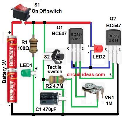
Parts List:
| Components | Values | Quantity |
|---|---|---|
| Resistors | 100Ω, 4.7M | 1 each |
| Preset 1 Meg | 1 | |
| Capacitor | Electrolytic 470µF 25V | 1 |
| Semiconductors | Transistor BC547 NPN | 2 |
| LED Red, Green | 1 each | |
| Tactile Switch | 1 | |
| On Off switch | 1 | |
| Battery 3V | 1 |
To begin with, this circuit works on RC time delay principle.
In this circuit, the resistor and capacitor show the delay time, while the preset allows fine adjustment of the delay; also two BC547 NPN transistors provide the required amplification.
LED1 indicates the power status, while LED2 indicates the output status, then the switch starts the timing process.
First, turning ON switch S1 supplies power to the circuit and at the same time, resistor R2 starts charging capacitor C1 slowly and because capacitor C1 has a high capacitance, it charges slowly.
Initially, the voltage at base of Q1 is low and so Q1 remains OFF and as time passes the capacitor voltage increases gradually.
When the base voltage reaches the transistors turn ON threshold, transistor Q1 turns ON and then Q1 then drives transistor Q2, causing it to turn ON and as a result, LED2 glows after the preset delay.
Meanwhile, LED1 indicates that the circuit has power.
The RC network shows the delay, which can reach about 30 minutes; so to set the delay, first adjust preset VR1 to its maximum value and then slowly fine-tune it until the circuit provides the desired 30 minute delay.
How to Build:
To build a 30 Minute Delay Timer Circuit using Transistors follow the below connection steps:
- First, take all the parts as shown in circuit diagram.
- Next, start with Q1 transistor base pin connected to R2, emitter of Q1 connected to base of Q2 and then collector of Q1 connected to collector of Q2.
- Then, Q2 transistor base pin connected to emitter of Q1, emitter of Q2 connected to ground and collector of Q2 connected to collector of Q1 and cathode of LED2 and supply.
- Also, one end of R2 resistor connects to one end of preset VR1 and other end of preset connects to base of Q1.
- Now capacitor C1 positive end connected to R2 and switch S2 and negative end connected to ground.
- Further, resistors R1 connected to LED1 for current limiting.
- Lastly, battery positive goes to switch S1 and battery negative goes to ground line.
Conclusion:
To conclude, this 30 Minute Delay Timer Circuit using transistors is simple and reliable, as it uses very few components and so delay time is easy to change.
The transistor based design keeps the circuit cost low, making it suitable for hobby and educational projects.
Also, with proper component selection, we can also achieve a long delay easily.

Leave a Reply