This article tell how to use simple parts like transistor, capacitor and diode to make Simple Delay Timer Circuit.
Also, this timer can wait some time like few seconds or minutes before turning something ON.
Hence, many circuits need this kind of delay timer to ensure operations happen in the correct order.
What is a delay timer circuit:
A delay timer circuit uses a relay to create a delay before turning ON an appliance.
Why Delay Timers are Important:
- By adding a few seconds or minutes of delay improves circuit performance; without this delay, the circuit may break or malfunction.
How it is Made:
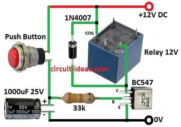
- We also need to join transistor and some simple parts to make delay happen and we can see this in circuit diagram below.
Parts Used for Delay Timer:
- Transistor stop too much current by using one small base resistor, but after the base resistor one more part is there it is capacitor which is very important for delay.
- Relay work like a load on transistors collector side.
Circuit Working:
Parts List:
| Components | Values | Quantity |
|---|---|---|
| Resistors | 33k 1/4 W CFR | 1 |
| Capacitor | Electrolytic 1000µF 25V | 1 |
| Semiconductors | Transistor BC547 | 1 |
| Diode 1N4007 | 1 | |
| Relay 12V | 1 | |
| Push button | 1 |
First, when we press the push button, power flows through the base resistor and turns ON the transistor and relay and at the same time, the capacitor starts charging fully.
Also, after we release the button, the transistor stays ON for some time by using the energy stored in the capacitor, which then gradually discharges.
Now relay is not turn ON until capacitor is fully empty, but how long transistor stay ON depends on size of capacitor.
Finally, a larger capacitor increases the time delay and a larger resistor keeps the transistor ON longer after we release the button; the base resistor also affects the delay.
Formulas and Calculations:
Formulas for Simple Delay Timer Circuit:
Here, we connect RC delay part to transistor base to find time delay (τ) of circuit, so we used this formula to find time constant:
τ = R × C
where:
- τ (tau) is time constant in seconds (s)
- R is resistor value in ohms (Ω)
- C is capacitor value in farads (F)
How to Calculate:
Step 1 Change capacitor to farads:
Example:
1000µF = 1000 × 10⁻⁶ F = 0.001 F
Step 2 Find time constant:
Use values in formula:
τ = 33,000Ω × 0.001F = 33 seconds
What It Means:
Hence, with these parts the circuit gives around 33 second delay from input change to output from transistor collectors change.
Note:
This number is just close idea, but actual delay can change little because of transistor behavior and small leakage currents.
Also, time constant (τ) means how long it take for capacitor voltage to reach around 63% of final voltage.
How to Build:
To build a Simple Delay Timer Circuit using a single transistor and a push button then follow the below mentioned steps:
Transistor Setup:
- First, connect transistor collector to positive supply of PCB and connect emitter to negative GND side of PCB.
Base Resistor Connection:
- Also, one side of base resistor connects to transistor base and other side of resistor connect to one side of push button.
Capacitor Connection:
- After that, connect positive longer leg of capacitor to other side of push button and negative short leg of capacitor connect to negative supply of PCB.
Relay Connection:
- Now connect relay coil pins between transistor collector and positive supply.
- Also, positive wire of power supply connect to PCBs positive line and negative wire connect to PCBs negative GND
- Press the push button for few seconds and see the relay turn ON.
- Then release the button and relay stay ON for some time depending on capacitor.
Modifications:
- To change delay time try bigger or smaller capacitor, we can also try different base resistor to change how long transistor stays ON.
Extra Tip:
- If we want longer delay try using two transistors in series for dual stage.
- Also, this make circuit more sensitive and let us use bigger resistors for more time.
- Lastly, before turning ON check twice all wires, polarities and component values to avoid mistake.
Conclusion:
Overall, these ideas help electronics hobbyists build a Simple Delay Timer Circuit that they can modify for different needs.
Also, try different parts and learn how delay change, as it is good for learning and making custom projects.
Leave a Reply